
Multi-stage hybrid evaporative cooling system

a technology of evaporative cooling system and multi-stage technology, which is applied in the direction of domestic cooling apparatus, lighting and heating apparatus, heating types, etc., can solve the problems of reducing the output power of these power systems, and achieve the effect of improving the efficiency of a multi-stage hybrid evaporative cooling system

Inactive Publication Date: 2010-08-03
S&T MFG CO
View PDF52 Cites 39 Cited by
  • Summary
  • Abstract
  • Description
  • Claims
  • Application Information

AI Technical Summary

Benefits of technology

[0009]The present invention provides and uses improved heat exchange, coolant evaporation, and novel refrigeration processes to improve the efficiency of a multi-stage hybrid evaporative cooling system.

Problems solved by technology

The power degradation curves of most power generating systems are such that as the temperature of air increases, the output power of these power systems decreases due to a decrease in the density of the air.

Method used


Image

  • Multi-stage hybrid evaporative cooling system
  • Multi-stage hybrid evaporative cooling system
  • Multi-stage hybrid evaporative cooling system

Examples


Embodiment Construction

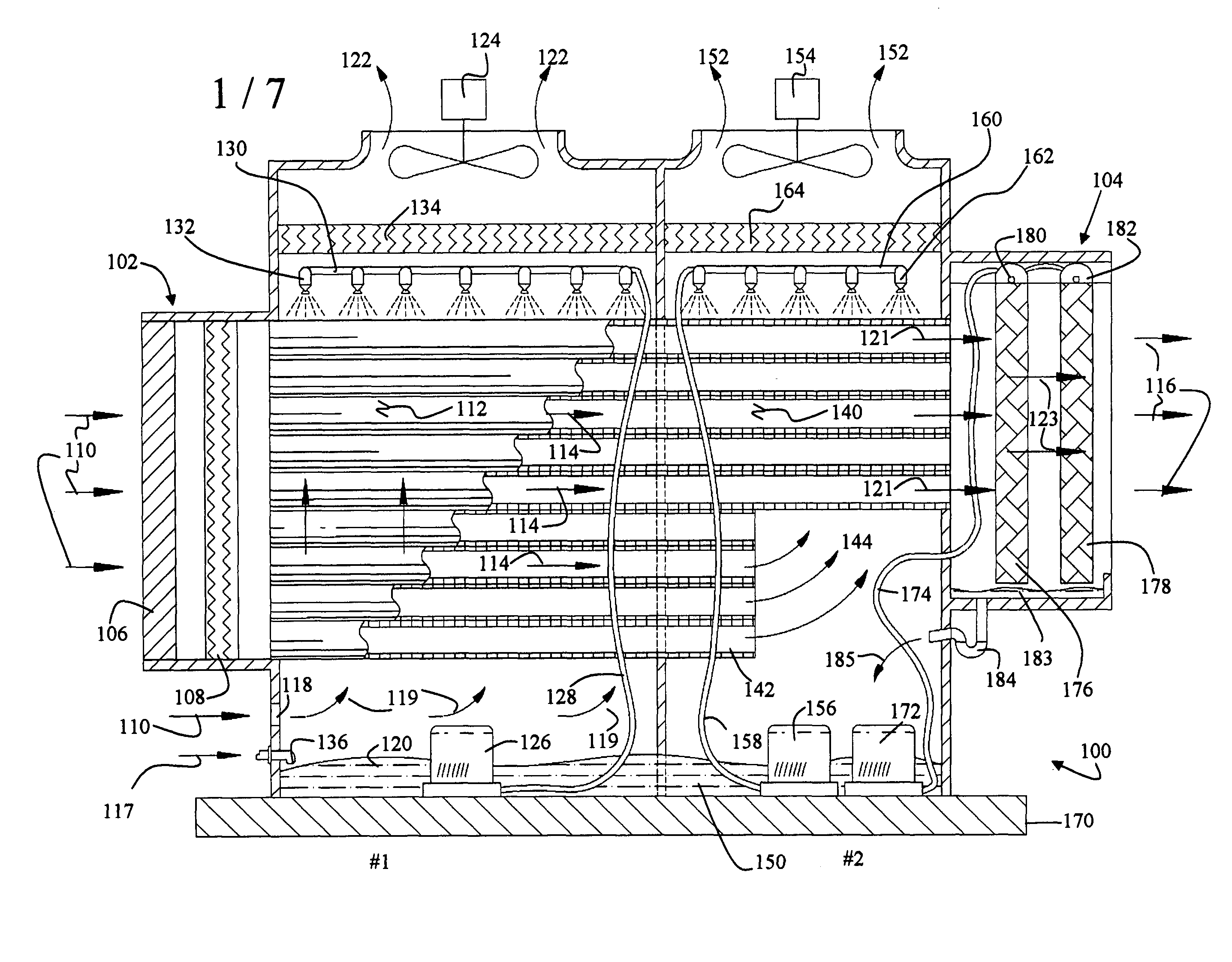
[0074]FIG. 1 is an exemplary illustration for an embodiment for a multi-stage hybrid evaporative cooling system 100 in accordance with the present invention that may be used as a standalone or with different power generating systems. As illustrated, system 100 is comprised of an air intake housing 102, one or more different isolated cooling chambers or stages (only two stages (#1 and #2) are shown), and an air discharge housing 104. The pluralities of different stages are isolated, with each stage comprised of a direct evaporative cooling subsystem and an indirect evaporative cooling subsystem. The sizes of each stage may vary based upon the thermal exchange capacity of each stage and the overall system.

[0075]Each stage within the multi-stage hybrid evaporative cooling system 100 is completely sealed from the next successive stage to isolate the wet-bulb temperature of one stage from a subsequent stage. The system 100 includes a set of heat exchangers for each stage, which are gener...


PUM


Abstract

A multi-stage hybrid evaporative cooling system is described as having a direct evaporative cooling subsystem and an indirect evaporative cooling subsystem having one of a horizontal and a vertical set of heat exchanger channels. The multi-stage hybrid evaporative cooling system with a horizontal set of heat exchanger channels has a portion of the horizontal heat exchanger channels partially extended into a next stage of the multi-stage system. The multi-stage hybrid evaporative cooling system with the vertical set of heat exchanger channels includes a first set of vertical set of heat exchanger channels spanning a substantial vertical height of the stage of the hybrid evaporative cooling system, and a second set spanning approximately half the height of the stage. The multi-stage hybrid evaporative cooling system further includes a refrigeration system for lowering the temperature of the indirect evaporative cooling subsystem air without affecting its pressure flow.

Description

BACKGROUND OF THE INVENTION[0001](1) Field of the Invention[0002]This invention relates to a method and apparatus for cooling systems and, more particularly, to a multi-stage hybrid evaporative cooling systems.[0003](2) Description of Related Art[0004]The power degradation curves of most power generating systems are such that as the temperature of air increases, the output power of these power systems decreases due to a decrease in the density of the air. In other words, most power generating systems require an intake of dense air for a more efficient operation in terms of greater power output. That is, the denser the air, the greater the operating efficiency of the power generators. It is well known that cooler air is denser than warmer air, and hence, today's power generating intake systems are generally coupled with air cooling systems, which provide the power generating units with cooler, and hence, more denser air for a more efficient operation of the power units. Therefore, it...

Claims


Application Information

Patent Timeline
Patent Type & Authority Patents(United States)
IPC IPC(8): F25D17/04F28D5/00F24F1/0059
CPCF24F5/0007F24F5/0035F28C1/14F28D5/00Y02B30/545F24F2001/0085F24F1/0007Y02B30/54Y02B30/70F24F1/0059
Inventor SCHLOM, LESLIE A.BECWAR, ANDREW J.
Owner S&T MFG CO
Learn More