Dimmable control circuit

a control circuit and dimming technology, applied in the direction of electric variable regulation, process and machine control, instruments, etc., can solve the problems of power consumption of the tube, too low reference voltage for uba2014, and the ballast activating the tub

Inactive Publication Date: 2010-07-27
LEE CHING CHUAN
View PDF7 Cites 0 Cited by
  • Summary
  • Abstract
  • Description
  • Claims
  • Application Information

AI Technical Summary

Benefits of technology

[0007]An objective of the present invention is to provide a novel dimmable control circuit to overcome the flaws of the known ones. The novel dimmable control circuit includes: an ac power source; a transformer; a rectifier circuit; a dimmable control chip; a voltage dividing circuit; a dimmable switch; a first resistor; a second resistor; and a half bridge power driving circuit, capable of outputting signals to drive a fluorescent tube, characterized in that said dimmable switch has a coactive variable resistor connected in parallel with said first resistor and said second resistor, and both said first resistor and said second resistor have the negative resistance temperature coefficient to achieve low temperature startup and high temperature protection.
[0015]To make it easier for our examiner to understand the objective of the invention, its structure, innovative features, and performance, we use a preferred embodiment together with the attached drawings for the detailed description of the invention.

Problems solved by technology

However, there exist flaws when the ballast activates the tube in low resistance of the variable resistor.
However, when the surrounding temperature goes down to, for example 0° C., the resistance of the known voltage dividing resistors having positive resistance temperature coefficient goes down as well, causing the reference voltage too low to activate the UBA2014.
Further more, when the surrounding temperature goes up, the resistance of the known voltage dividing resistors having positive resistance temperature coefficient goes up as well, causing the reference voltage to rise up and as a result the output operating frequency of the UBA2014 will be lowered down, and the power consumption of the tube will increase.

Method used


Image

  • Dimmable control circuit
  • Dimmable control circuit

Examples


Embodiment Construction

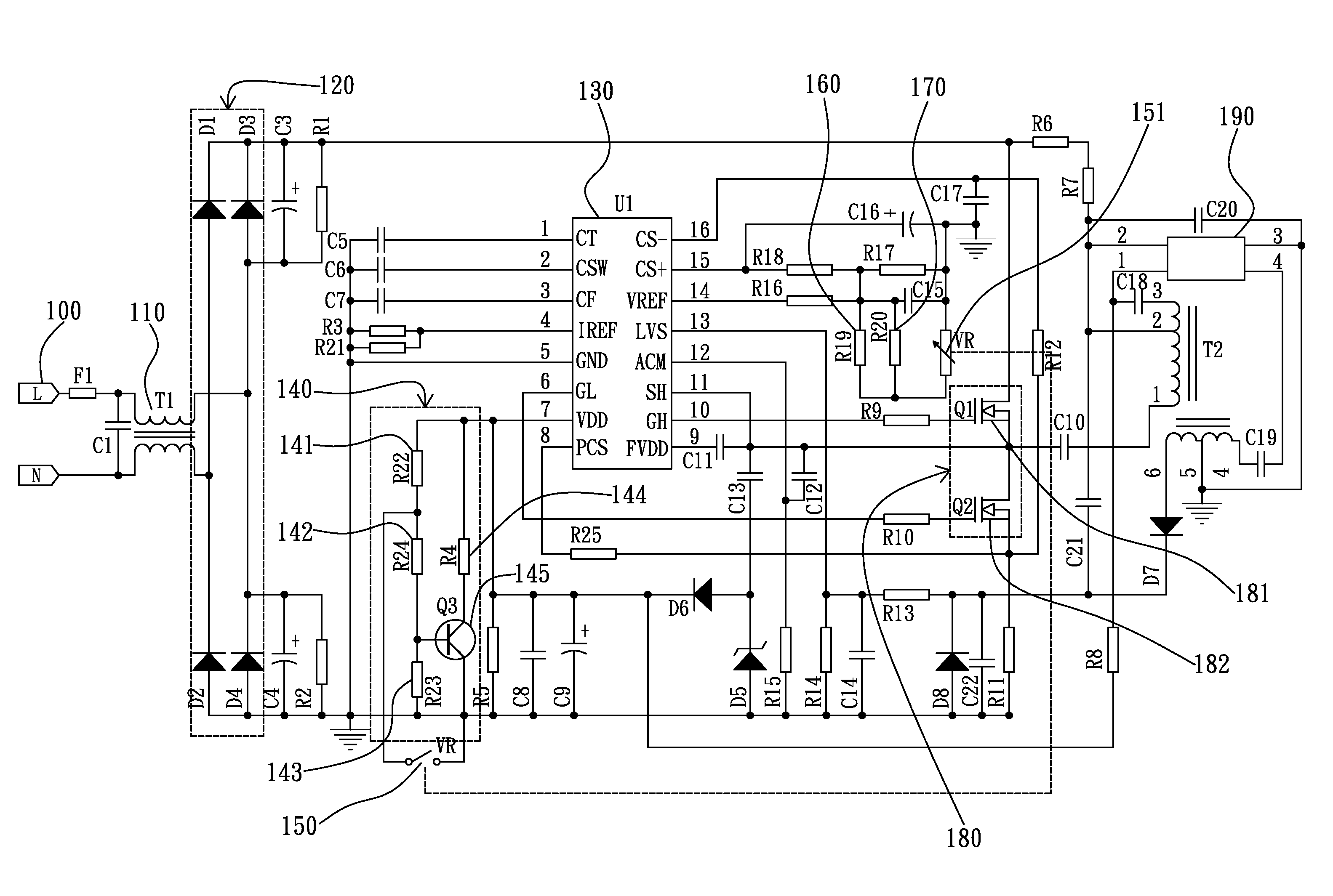
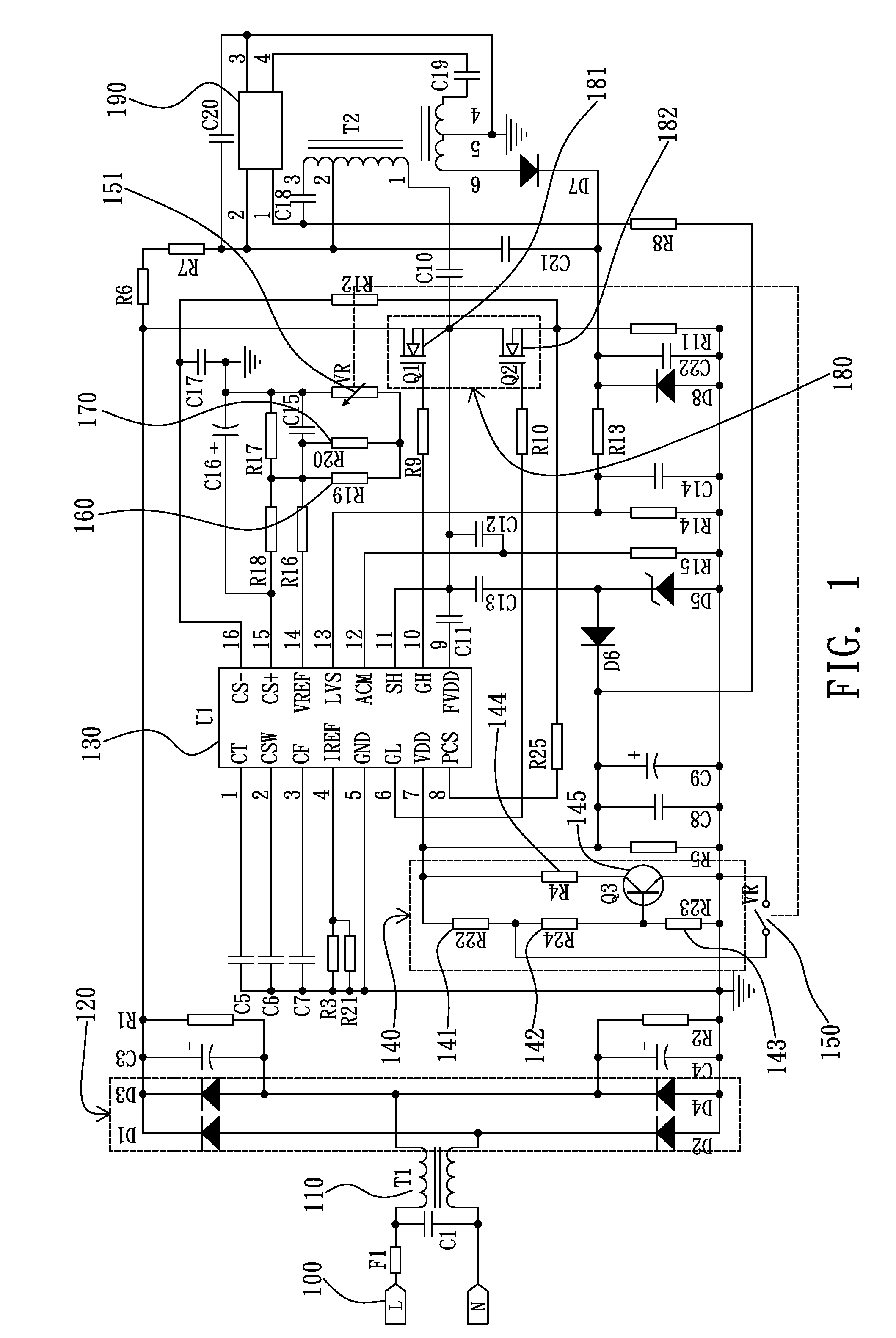
[0017]FIG. 1 shows one possible implementation of the present invention. As shown in the drawing, the dimmable control circuit comprises an ac power source 100, a transformer 110, a rectifier circuit 120, a dimmable control chip 130, a voltage dividing circuit 140, a dimmable switch 150, a first resistor 160, a second resistor 170, and a half bridge power driving circuit 180.

[0018]Wherein, said ac power source 100 can be rated as but not limited to AC120˜230V.

[0019]Said transformer 110, coupled to said ac power source 100, is capable of stepping down the amplitude of said ac power source 100, and then delivers the stepped down ac power to said rectifier circuit 120 for rectification.

[0020]Said rectifier circuit 120, which can be but not limited to a half wave or full wave rectifier circuit, is capable of converting the stepped down ac power from said transformer 110 to dc power, which is then filtered to be the power supply of said dimmable control chip 130, voltage dividing circuit...


PUM


Abstract

A dimmable control circuit, having an ac power source; a transformer; a rectifier circuit; a dimmable control chip; a voltage dividing circuit; a dimmable switch; a first resistor; a second resistor; and a half bridge power driving circuit, capable of outputting signals to drive a fluorescent tube, characterized in that the said dimmable switch has a coactive variable resistor connected in parallel with the first resistor and the second resistor, and both the first resistor and the second resistor have the negative resistance temperature coefficient to achieve low temperature startup and high temperature operation.

Description

BACKGROUND OF THE INVENTION[0001]1. Field of the Invention[0002]The present invention relates to a dimmable control circuit, and more particularly to a dimmable control circuit having a first resistor and a second resistor, both with the negative resistance temperature coefficient, to achieve low temperature startup and high temperature operation.[0003]2. Description of the Related Art[0004]At present, the common dimmable electronic ballast usually works on the brightness control of the fluorescent tube in an order from dark to bright. That is, when the user turns on the power switch having a coactive variable resistor, the ballast will first work in low resistance of the variable resistor causing dim brightness of the tube, and then work in higher resistance of the variable resistor causing the tube brighter as the user turns the variable resistor clockwise. However, there exist flaws when the ballast activates the tube in low resistance of the variable resistor.[0005]Besides, the ...

Claims


Application Information

Patent Timeline
Patent Type & Authority Patents(United States)
IPC IPC(8): H05B41/36
CPCH05B41/2986H05B41/382Y02B20/204Y02B20/00Y10S315/04
Inventor LEE, CHING CHUAN
Owner LEE CHING CHUAN
Why Eureka
Try Eureka