
Split bottom bracket

a bottom bracket and split technology, applied in the direction of friction roller based transmission, steering device, cycle equipment, etc., can solve the problems of increasing the weight of the assembly, the unitary structure cannot be easily inserted through the relatively close fitting standard-size bottom bracket, and the ineffective use of standard-size single-piece crank shaft assemblies

Inactive Publication Date: 2010-07-27
CANNONDALE BICYCLE CORPORATION
View PDF25 Cites 14 Cited by
  • Summary
  • Abstract
  • Description
  • Claims
  • Application Information

AI Technical Summary

Benefits of technology

"The present invention provides a bottom bracket assembly for a bicycle frame that is usable with a single-piece crank shaft assembly. The assembly includes an upper portion and a lower portion that can be detachably connected together. The lower portion has mounting elements that can be securely affixed to the upper portion using mounting devices, such as screws or bolts. The assembly is designed to provide increased versatility and sealing while still maintaining proper bearing alignment and tension. The lower portion can be completely detached from the upper portion and adjusted on both sides. The invention also provides a method for maintaining the crank shaft assembly in the bottom bracket. Overall, the invention provides a light weight and versatile bottom bracket assembly for bicycles that ensures proper bearing alignment and tension while still being adjustable and sealing."

Problems solved by technology

The limitation of known systems is that, while they may effectively be used with multi-piece crank shaft assemblies, they cannot effectively be used with standard-size single-piece crank shaft assemblies.
The result is that the unitary structure cannot readily be inserted through the relatively close fitting standard-size bottom bracket.
While it is possible to manufacture an oversized bottom bracket assembly, this is undesirable as this greatly increases the weight of the assembly.
A number of systems have attempted to provide additional versatility for the bottom bracket assembly with limited success.
While this does provide some versatility for insertion and removal of the crank shaft assembly, a major drawback for these systems is fatigue of the bottom bracket assembly.
This is especially problematic for frequent changing / adjustment of the crank shaft assembly.
The problem is fundamental to the design because the bottom bracket assembly necessarily must flex open and close when changing or adjusting the crank shaft assembly leading to relatively early failure of the bottom bracket.
Additionally, there is also a constant residual stress induced in the bottom bracket, reducing the ability of the assembly to withstand extreme outside forces.
While this assembly provides additional versatility, the strength of the device is seriously compromised, which is especially critical in high impact applications, such as mountain biking and off-road applications.
The reference teaches that a brazing technique may be used, however, this requires increased labor and cost and still does not provide adequate strength.
Another problem with this arrangement is that if the tubes are provided as a composite material, the brazing technique cannot be used.
While this system does provide for increased versatility, this system does not provide adequate adjustment and sealing of the bottom bracket assembly.
This system only allows for tightening of one side of the bottom bracket therefore, when the hinged side loosens over time, there is no way to tighten it.
For mountain biking and off-road applications, this will allow an unacceptable amount of dirt and / or debris into the bottom bracket resulting in damage and decreased performance.
In addition, a hinge will, over time, be subject to corrosion, thereby making opening and closing difficult and negatively affecting the strength of the bracket assembly.
Also, optimum bearing pre-load is difficult to obtain consistently, and so as to allow for free rotation of the bearings, the hinged side must be minimally tightened, thereby allowing the possibility of unexpected loosening of the bolts due to variable loading and vibration and also unexpected movement of the crank shaft assembly, which is highly undesirable.

Method used


Image

  • Split bottom bracket
  • Split bottom bracket
  • Split bottom bracket

Examples


Embodiment Construction

[0026]Referring now to the drawings, wherein like reference numerals designate corresponding structure throughout the views.

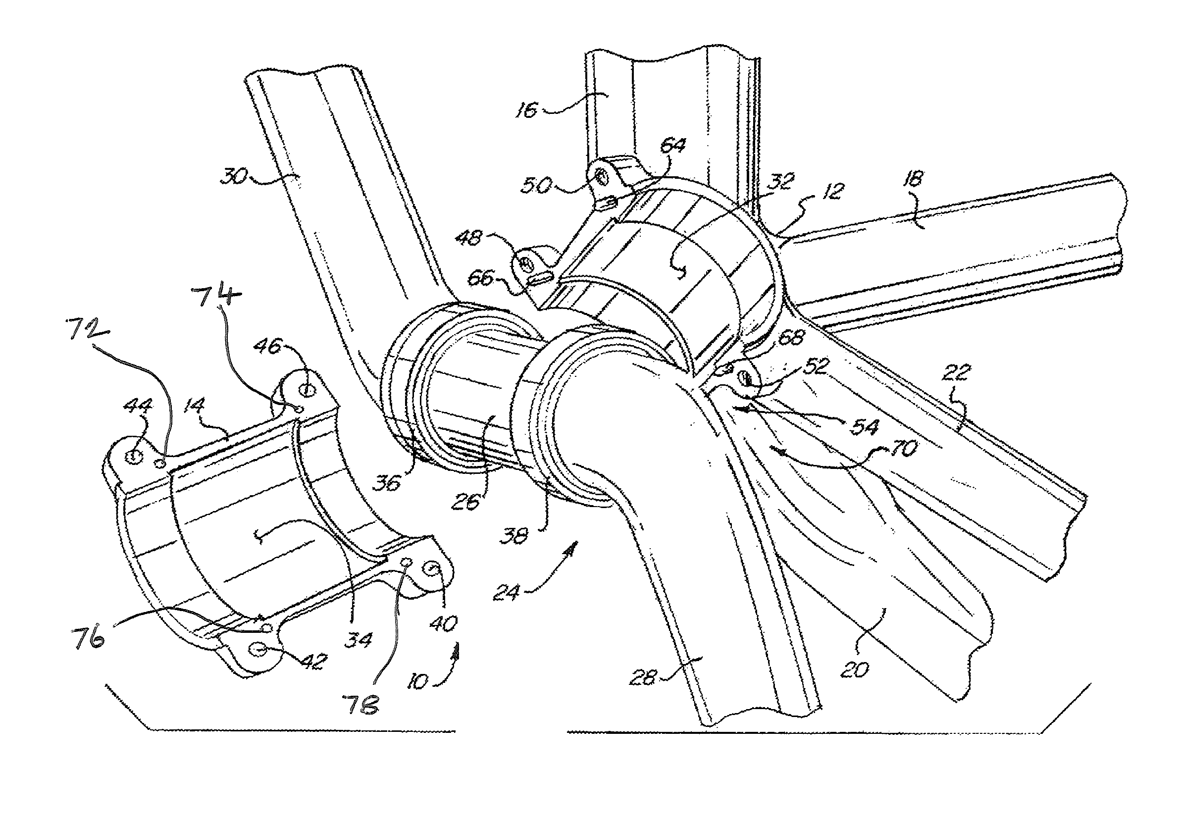
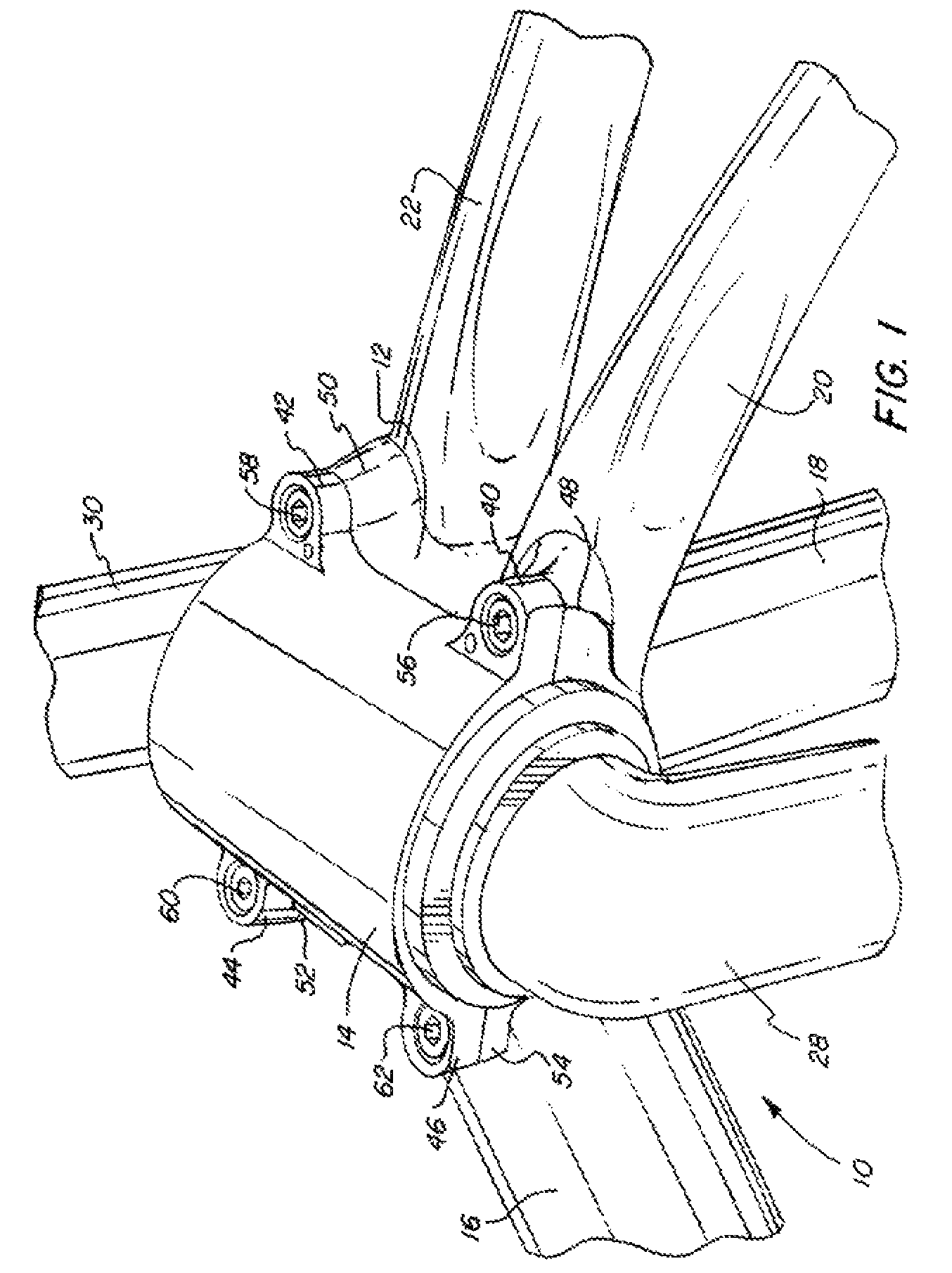
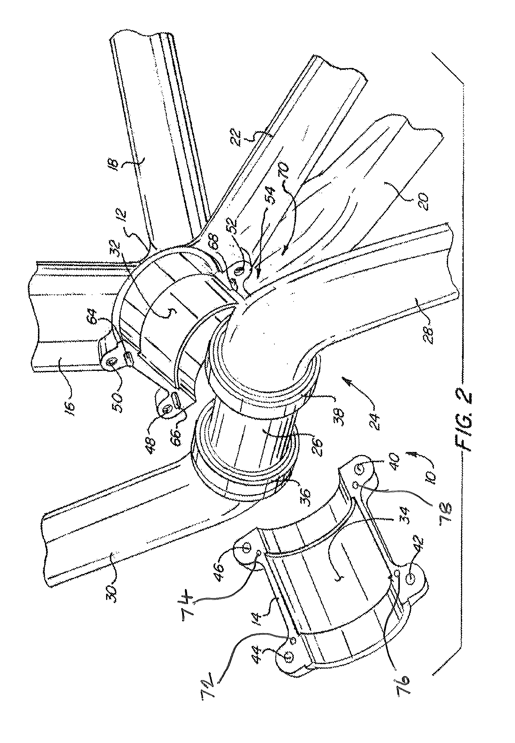
[0027]FIG. 1 is an illustration of the split bottom bracket assembly 10 according to one advantageous embodiment of the present invention. Split bottom bracket assembly 10 is shown assembled and comprises an upper portion 12 and lower portion 14. Upper portion 12 is formed integrally with the bicycle frame including tubes 16, 18, 20, 22. Upper portion 12 and lower portion 14 are coupled together and capture crank shaft assembly 24 (FIG. 2) therebetween. Crank shaft assembly 24 typically includes a crank shaft 26 along with pedal arms 28, 30 extending from crank shaft 26.

[0028]As seen in FIGS. 2 and 3, split bottom bracket assembly 10 is shown disassembled with crank shaft assembly 24 shown removed from split bottom bracket assembly 10. From this view it can be seen that upper portion 12 is provided having a semi-circular interior surface 32, while lower portion...


PUM


Abstract

A bottom bracket assembly for use on a bicycle, the assembly provided as a split bracket assembly with an upper portion formed integrally with the bicycle frame and a lower portion detachably connectable to the upper portion, the lower portion completely removable from the upper portion. The bottom bracket assembly provided to capture a crank shaft therein with associated bearings to facilitate the rotation of the crank shaft assembly.

Description

FIELD OF THE INVENTION[0001]The invention relates to a bottom bracket assembly used for supporting a crank assembly used on a bicycle, and more particularly, to a bottom bracket assembly that has a split housing allowing a lower half of the housing to be removed from the bicycle.BACKGROUND OF THE INVENTION[0002]Bicycles are typically provided with a crank shaft assembly that propels the bicycle when operated by a rider. Crank assemblies typically comprise a crank shaft that extends through a bottom bracket formed into the lower portion of a bicycle frame and pedal arms that are coupled to the crank shaft.[0003]The limitation of known systems is that, while they may effectively be used with multi-piece crank shaft assemblies, they cannot effectively be used with standard-size single-piece crank shaft assemblies. For example, rather than have a crank shaft assembly comprise a crank shaft and two detachable pedal arms, it may be desired based upon the application to provide an integrat...

Claims


Application Information

Patent Timeline
Patent Type & Authority Patents(United States)
IPC IPC(8): B62K19/34B62M3/00
CPCB62K19/34Y10T74/2164
Inventor DODMAN, CHRISTOPHER P.DETWILER, CURTIS WAYNE
Owner CANNONDALE BICYCLE CORPORATION
Learn More