Servo-press with energy management

a technology of energy management and servo-presses, which is applied in the direction of forging presses, forging/pressing/hammering apparatuses, and shape safety devices, etc., can solve the problems of large energy storage requirements, high cost, and inability to meet the needs of auxiliary drives, so as to reduce costs and reduce the effect of conversion arrangemen

Inactive Publication Date: 2010-07-13
SCHULER PRESSEN GMBH & CO KG
View PDF7 Cites 7 Cited by
  • Summary
  • Abstract
  • Description
  • Claims
  • Application Information

AI Technical Summary

Benefits of technology

[0011]The press installation according to the invention provides an intermediate DC power supply circuit connected to the power supply grid, or network, by way of a controlled power converter. This intermediate DC power supply circuit supplies power to all servo-drives for the plungers and all the servo-drives of the auxiliary equipment such as part transport arrangements or intermediate storage devices, drawing dies, etc. The respective servo-drives are all supplied with power from the same intermediate DC power supply circuit preferably via DC / AC converter devices. The intermediate DC power supply circuit also includes a fly-wheel storage device which is capable of taking energy from the intermediate DC power supply circuit and also to return energy to the intermediate DC power supply circuit. A supervisory control arrangement controls the operation of the power converter devices. In this way, the variations of the power withdrawn from the electrical power supply grid can be minimized and the overall-power requirements for the whole press installation remain essentially constant. This substantially reduces the resistance losses in the power supply lines which increase with the square of the current flow. In addition to a reduction in losses, the power supply grid quality is increased since load-induced voltage variations in the power supply are minimized. Furthermore, expenses for the power supply connections are substantially reduced since they do not need to be de-energized for the peak power requirements of the presses, but only for the average power requirements. With the intermediate DC voltage power supply circuit and the DC / AC converters disposed between the press drives and fly-wheel, the servo-motors of the press drives and the fly-wheel can be operated independently at different speeds. The converters practically form an electrical infinitely variable transmission.
[0030]With the limitation of the current as power supply to the converter arrangement and the current or power limitation for the return to the grid, for the converter arrangement building components designed for certain normal currents and peak currents can be used which are substantially lower than the peak currents needed by the press installation. As a result, the converter arrangement may be smaller and the costs therefore are reduced.
[0031]The fly-wheel storage device is, with respect to the storage capacity, so dimensioned that a predetermined partial amount of its maximum capacity is sufficient to buffer all load changes occurring in the press installation. The difference between this partial amount and the maximum capacity of the fly-wheel storage device corresponds to the maximum brake energy to be taken up by the fly-wheel storage device driving an emergency shut down of the press installation. In this way, it is made sure, on one hand, that the fly-wheel storage device can be used for providing for a totally uniform power supply grid loading whereas, on the other hand, all drives of the press installation can be shut down in a controlled, synchronous manner. After an emergency shut-down of the press, the fly-wheel storage device runs at maximum speed. There is no need to return power to the power supply grid.
[0032]Alternatively, the fly-wheel storage device may be dimensioned somewhat smaller, so that during an emergency stop it can accept at least a large part of the brake energy released by the press installation during an emergency shut down while the system is changed from grid loading to supplying power to the grid in a controlled manner.
[0033]The control arrangement may be such that the power used at the servo-drive arrangements is recorded. This can be done, for example, by measuring the voltages and currents over time as provided to the servo-motors. Additionally or alternatively, power measuring devices may be provided at the converter arrangements. If, for example, the DC currents entering the converter arrangements and the respective voltages are measured, the effective power can be determined herefrom in a simple and safe manner.
[0036]The control arrangement may additionally monitor the voltage of the intermediate DC voltage circuit. This voltage does not necessarily have to be kept constant. It is, however, expedient to maintain that voltage within reasonable limits so as to avoid excessive voltages on one hand and, on the other, to prevent a voltage drop to values insufficient for the operation of the converter.

Problems solved by technology

As a result, it stores substantially more energy than is necessary for a single deformation procedure.
At least, if the fly-wheel is firmly connected to the circular drive a correspondingly large amount of energy needs to be destroyed when the press is stopped.
The connection between the main drives and the auxiliary drives and the drawing dies by way of guide shafts and energy exchange modules however is quite expensive.
Servo-motor controlled machines cause varying loads on the power supply grid.
This may cause excessive loads on the power supply grids.
This may cause a problem occasionally already with a single machine, but is very problematic if several machines working in parallel are at peak loads all at the same time.
In spite of efficient drive techniques, this may lead to energy losses which need to be avoided.

Method used


Image

  • Servo-press with energy management
  • Servo-press with energy management
  • Servo-press with energy management

Examples


Embodiment Construction

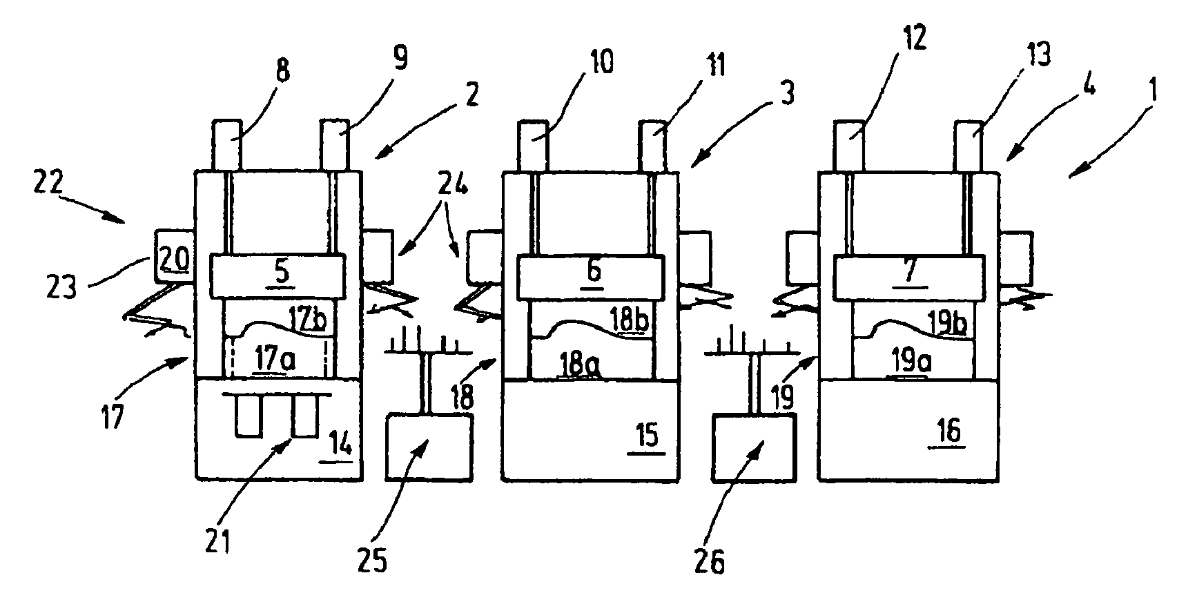
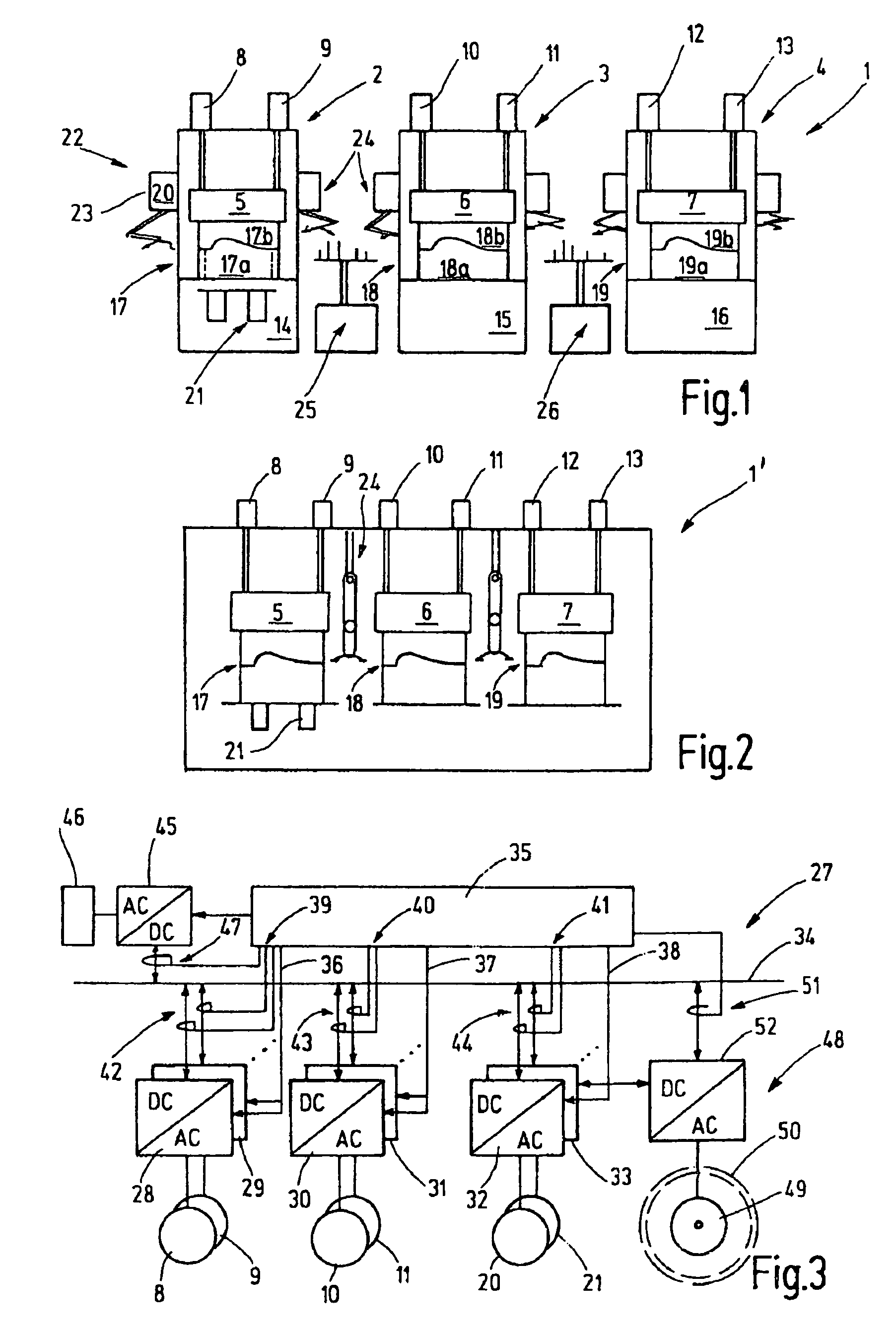
[0044]FIG. 1 shows a press installation 1 including at least one, but in the shown example several, individual presses 2, 3, 4. The presses are provided for a stepwise deforming of a workpiece, for example, a metal sheet such as a vehicle body part, or similar, which is treated in one press after another. The press 2 is a drawing press, whereas, the presses 3 and 4 are follow-up presses. Each press 2, 3, 4 has a plunger 5, 6, 7. For driving the plunger 5 at least one, but preferably several servo-motors 8, 9 are provided. Likewise, the plungers 6, 7 are driven by servo-motors 10, 11, 12, 13. The servo-motors 8 to 13 drive the plunger 5, 6, 7 by means of a suitable drive such as a spindle drive. Also other drives may be used such as linear motors or similar drives. Below the plunger 5 to 7 there is in each case a press table 14, 15, 16. For deforming the workpiece, tools 17, 18, 19 are used, each including a ball arm part 17a, 18a, 19a disposed on a press table 14, 15, 16. The respec...


PUM

PropertyMeasurementUnit
press angleaaaaaaaaaa
DC voltageaaaaaaaaaa
voltageaaaaaaaaaa

Abstract

In a press installation including a number of presses with servo-drives for operating the presses and auxiliary equipment such as workpiece handling devices wherein an energy management system is provided including a DC voltage intermediate circuit connected to a power supply grid via an AC / DC converter and to the servo-drives via servo-converters, a fly-wheel storage device is connected to the intermediate circuit for supplying energy thereto and recapturing energy therefrom under the control of a control arrangement which controls the flow of power between the intermediate circuit, the servo-drives, the fly-wheel storage device and the power supply grid.

Description

CROSS-REFERENCE TO RELATED APPLICATION[0001]This application claims the priority benefits of German Application No. 10 2006 033 562.7 filed Jul. 20, 2006.BACKGROUND OF THE INVENTION[0002]This invention resides in a press installation and in a method of operating such an installation. The invention relates particularly to large part-press installations, for example, in the form of press-lines are on multistage large part presses in the form of transfer presses.[0003]Conventional presses include a mechanical press drive with an electric drive motor and a fly-wheel which serves as an energy storage device. A crank drive, a circular drive, an elbow drive or a similar drive converts the rotation of the fly-wheel into a back and forth movement of a plunger. The fly-wheel is so large dimensioned that its speed changes remains tolerable. As a result, it stores substantially more energy than is necessary for a single deformation procedure. At least, if the fly-wheel is firmly connected to th...

Claims


Application Information

Patent Timeline
Patent Type & Authority Patents(United States)
IPC IPC(8): B21C51/00
CPCB30B15/148B21D43/05
Inventor SCHMEINK, MARTIN
Owner SCHULER PRESSEN GMBH & CO KG
Why Eureka
Try Eureka