System and method for use in a combined or rankine cycle power plant

a technology of power plant and power generation system, which is applied in the direction of machines/engines, domestic cooling devices, lighting and heating devices, etc., can solve the problem that about 30% of the generated energy is wasted in the condenser of the power plan

Inactive Publication Date: 2010-07-06
GENERAL ELECTRIC CO
View PDF15 Cites 2 Cited by
  • Summary
  • Abstract
  • Description
  • Claims
  • Application Information

AI Technical Summary

Problems solved by technology

In combined cycle power plants, it has been seen that about 30% of the generated energy is wasted in condensers of the power plants because of the thermodynamic requirement to reject heat.

Method used


Image

  • System and method for use in a combined or rankine cycle power plant
  • System and method for use in a combined or rankine cycle power plant
  • System and method for use in a combined or rankine cycle power plant

Examples


Embodiment Construction

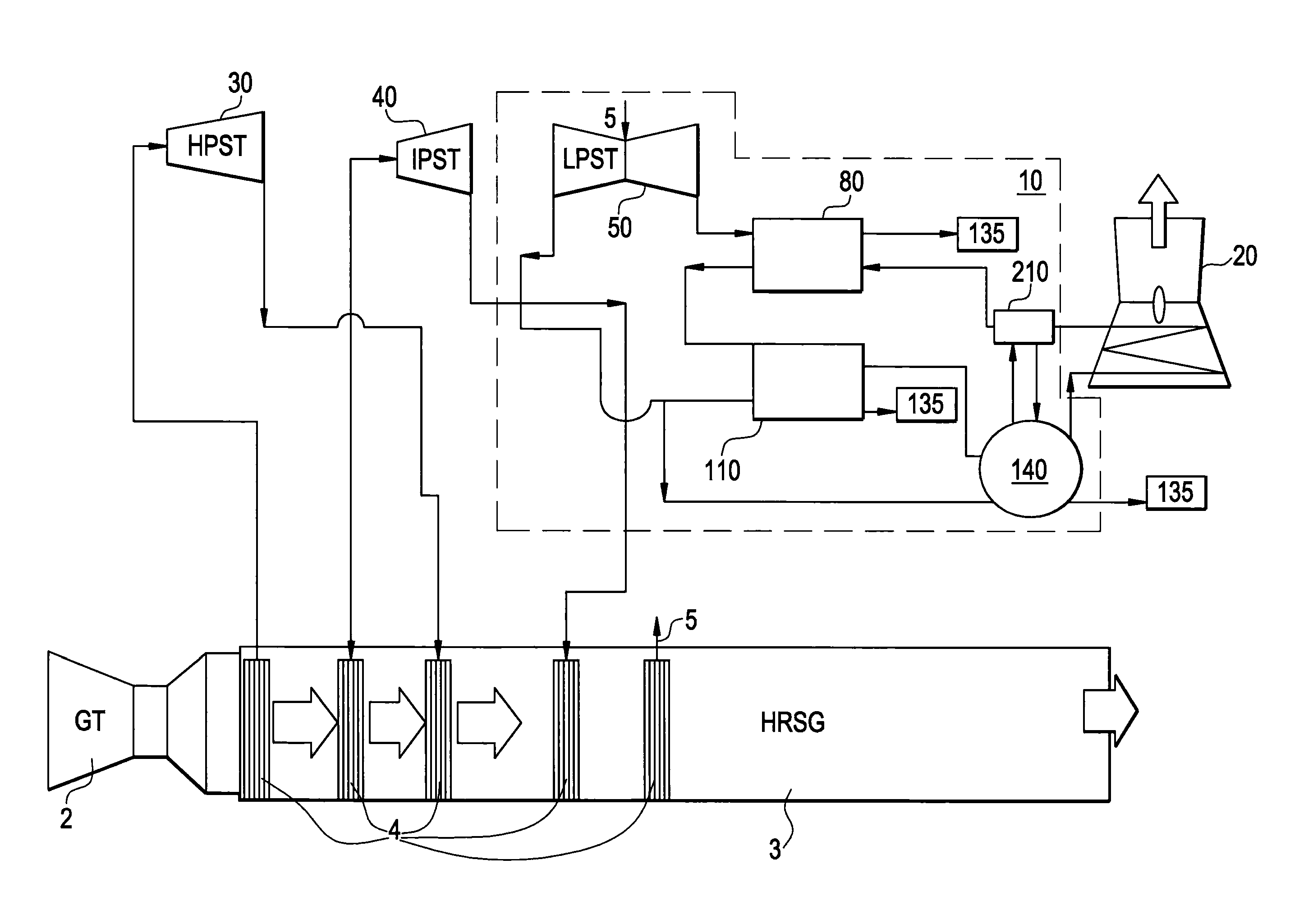
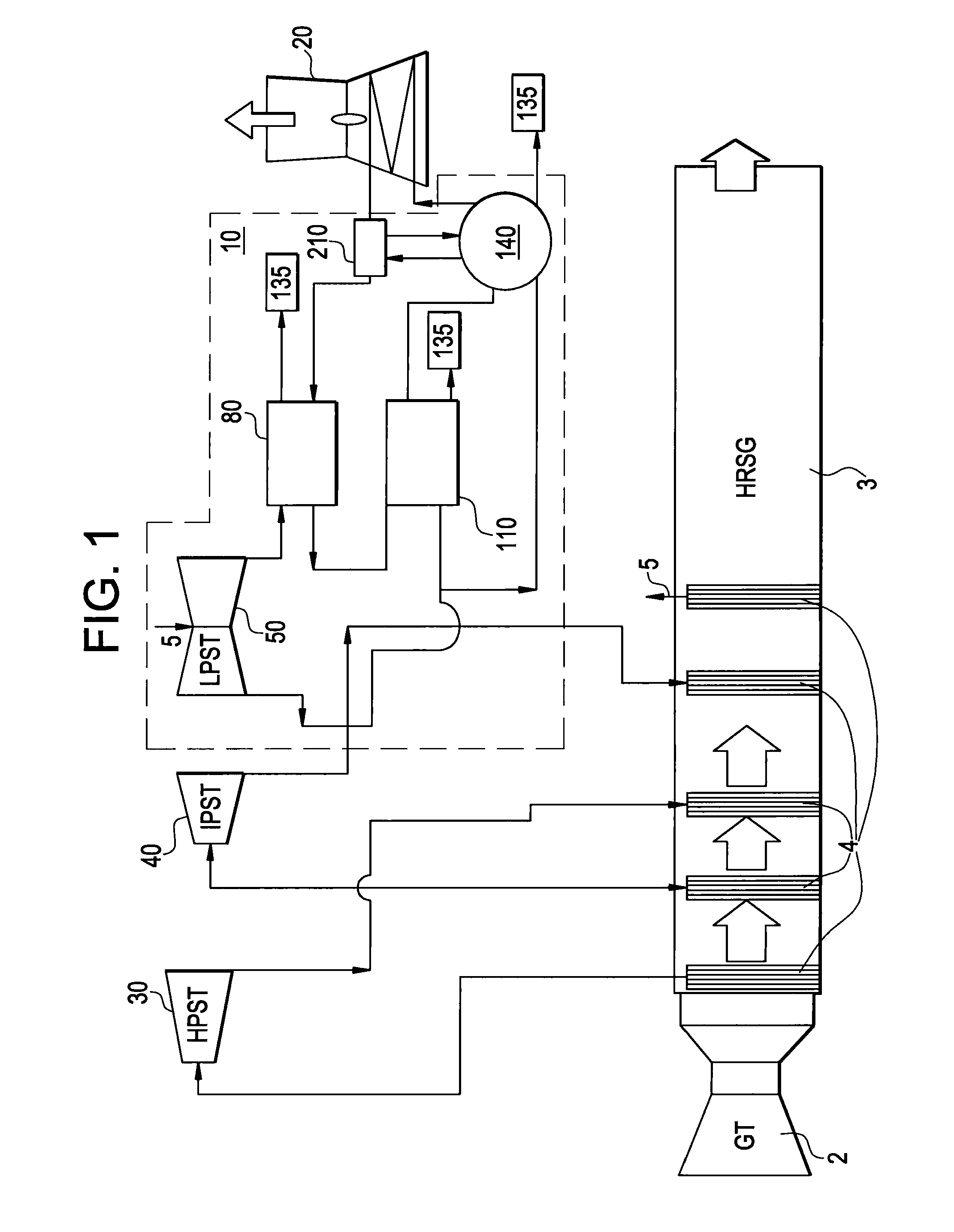
[0012]With reference to FIG. 1, a system 10 for use in, e.g., a combined cycle power plant or, alternately, a rankine cycle power plant, is provided. The exemplary combined or rankine cycle power plant may include a gas turbine 2, which generates heat during operations thereof, a heat recovery steam generator (HRSG) 3, which is coupled to the gas turbine 2, a cooling tower 20, a high pressure steam turbine (HPST) 30, an intermediate pressure steam turbine (IPST) 40 and a low pressure steam turbine (LPST) 50. The HRSG 3 generates steam by way of the heat generated by the gas turbine 2 and includes heat exchangers 4, such as super heaters, evaporators, and pre-heaters, which are disposed along an axis thereof, and by which portions of the generated steam are diverted to the HPST 30, the IPST 40 and the LPST 50. The HPST 30, the IPST 40 and the LPST 50 generate power, such as electricity, by way of the diverted steam, and output spent steam supplies. An operation of the system 10 relat...


PUM


Abstract

A system is provided and includes a first condenser configured to fluidly receive a first steam supply and tower water and to output a first water supply, a second condenser configured to fluidly receive a first portion of a second steam supply and the first water supply and to output a second water supply, and a vapor-absorption-machine (VAM) configured to fluidly receive a second portion of the second steam supply and the second water supply by which a refrigeration cycle is conducted to thereby cool at least one of the tower water and a third water supply used to cool the tower water.

Description

BACKGROUND OF THE INVENTION[0001]1. Field of the Invention[0002]Aspects of the present invention are directed to a system and a method for use in a power plant and, more particularly, to a system and a method for use in a combined or rankine cycle power plant.[0003]2. Description of the Background[0004]In combined cycle power plants, it has been seen that about 30% of the generated energy is wasted in condensers of the power plants because of the thermodynamic requirement to reject heat.[0005]This problem has been addressed in some cases by employing a vapor absorption system that is used to recover the heat rejected in the condenser to produce a refrigeration effect. This refrigeration effect has been used to chill the inlet air to the gas turbine in a gas turbine and steam turbine combined cycle installation. In other cases, this problem has been addressed by employing a Kalina bottoming cycle in a combined cycle power plant.SUMMARY OF THE INVENTION[0006]In accordance with an aspe...

Claims


Application Information

Patent Timeline
Patent Type & Authority Patents(United States)
IPC IPC(8): F02C6/00
CPCF01K9/003F01K23/10Y02E20/16
Inventor CHANDRABOSE, SHINOJ VAKKAYILRANCRUEL, DIEGO FERNANDOGOVINDAN, PRAKASH NARAYANSHARMA, ANIL KUMAR
Owner GENERAL ELECTRIC CO
Why Eureka
Try Eureka