
Modular tile with controlled deflection

a module and tile technology, applied in carpet cleaners, applications, ways, etc., can solve the problems of concrete providing no “give” during use, concrete is easy to construct and provide long-term wear, and many people are injured, so as to and facilitate controlled deflection of primary post structures

Inactive Publication Date: 2010-07-06
CONNOR SPORT COURT INT
View PDF79 Cites 61 Cited by
  • Summary
  • Abstract
  • Description
  • Claims
  • Application Information

AI Technical Summary

Benefits of technology

"The present invention provides a new type of tile that can be used to create a modular floor covering. These tiles have a unique design that allows them to interlock with each other and provide controlled deflection of their support members. This results in a floor covering that is more stable and can withstand more weight, making it a better choice for use in high-density areas. The tiles can also be easily manufactured and installed, making them a more practical option for flooring projects."

Problems solved by technology

For example, concrete flooring is easy to construct and provides long term wear.
However, the concrete provides no “give” during use and many people are injured each year during sporting events due to falls and other mishaps.
The wood floors, however, are expensive to install and require continued maintenance to keep them in good condition.
If a tile is damaged it may easily be replaced.
In particular, current synthetic flooring does not include characteristics of predictable and controlled deflection within the synthetic tiles under certain predicted load ranges and impacts on the synthetic flooring.
Further, the current synthetic flooring materials do not exhibit the spring or bounce characteristics found in wood flooring.

Method used


Image

  • Modular tile with controlled deflection
  • Modular tile with controlled deflection
  • Modular tile with controlled deflection

Examples


Embodiment Construction

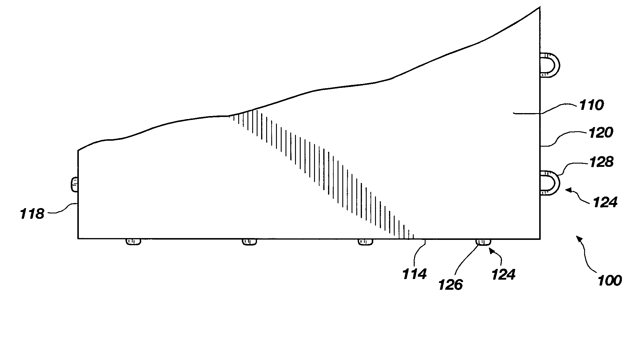
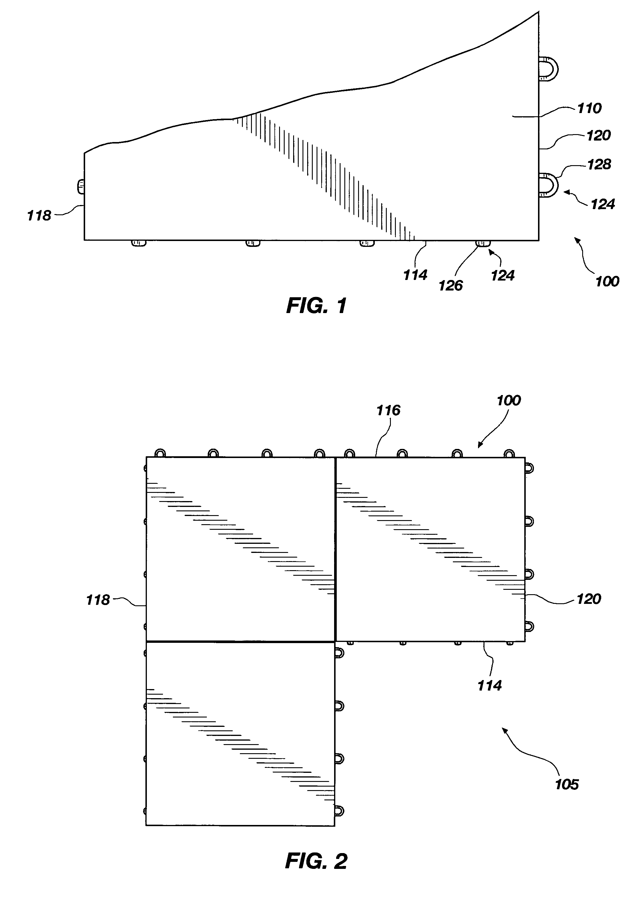
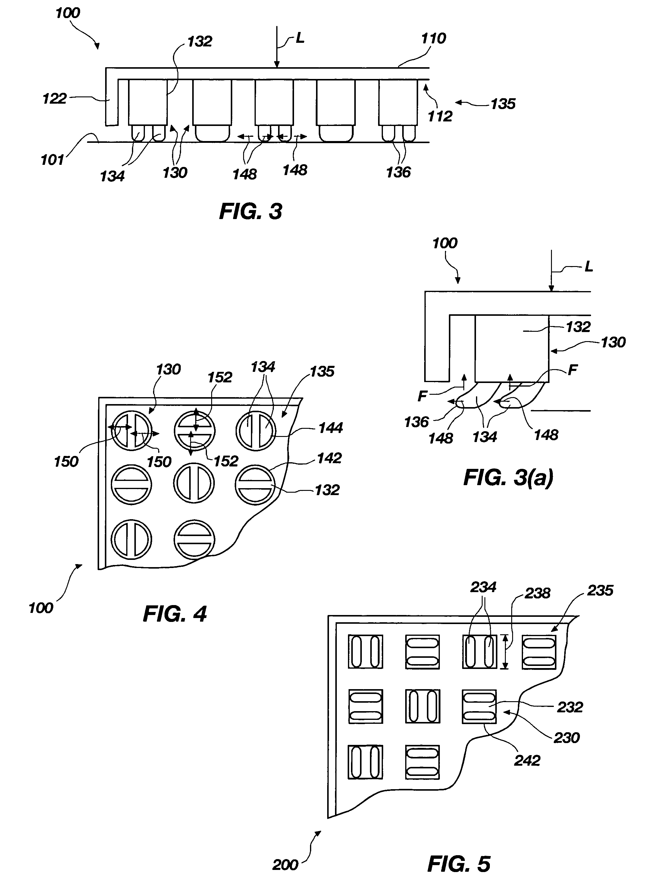
[0030]The following detailed description of exemplary embodiments of the invention makes reference to the accompanying drawings, which form a part hereof and in which are shown, by way of illustration, exemplary embodiments in which the invention may be practiced. While these exemplary embodiments are described in sufficient detail to enable those skilled in the art practice the invention, it should be understood that other embodiments may be realized and that various changes to the invention may be made without departing from the spirit and scope of the present invention. Thus, the following more detailed description of the embodiments of the present invention, as represented in FIGS. 1 through 16, is not intended to limit the scope of the invention, as claimed, but is presented for purposes of illustration only and not limitation to describe the features and characteristics of the present invention, to set forth the best mode of operation of the invention, and to sufficiently enab...


PUM

PropertyMeasurementUnit
heightaaaaaaaaaa
spring forceaaaaaaaaaa
resilientaaaaaaaaaa

Abstract

A modular tile configured to interlock with multiple tiles to form a modular floor covering over a floor. The tile includes a top surface having a periphery defining side walls extending downward from the top surface, the side walls having a coupling portion configured to couple with other tiles adjacent thereto to form the modular floor covering. The tile also includes a bottom side, opposite the top surface, having a support grid including an array of downward extending polymeric post structures, at least some of the post structures including at least one resilient end portion with a radial end surface configured to be positioned against the floor to facilitate controlled deflection of the post structures. The post structures may comprise primary and secondary post structures, with the secondary post structures limiting the deflection of the primary post structures.

Description

RELATED APPLICATIONS[0001]This application claims priority to U.S. Provisional Patent Application Ser. No. 60 / 547,489, filed Feb. 25, 2004, and entitled, “Modular Tile with Controlled Deflection,” which is incorporated by reference in its entirety herein.FIELD OF THE INVENTION[0002]The present invention relates generally to modular synthetic tiles for use as a floor covering and, more particularly, the present invention relates to a support grid in the tiles.BACKGROUND OF THE INVENTION AND RELATED ART[0003]Numerous types of flooring have been used to create playing areas for such sports as basketball and tennis, as well as for other purposes. These flooring assemblies include concrete, asphalt, wood and other materials which have varying characteristics. For each type of flooring, there are corresponding advantages and disadvantages. For example, concrete flooring is easy to construct and provides long term wear. However, the concrete provides no “give” during use and many people ar...

Claims


Application Information

Patent Timeline
Patent Type & Authority Patents(United States)
IPC IPC(8): E04F11/16E04F13/08E06B3/54
CPCE01C5/20E01C13/045E04F15/225E04B5/43Y10T428/24802E04F15/22E04F15/105E04F2201/091E04F2201/096E01C13/04
Inventor JENKINS, MARK L.SHAPIRO, JEREMIAHFORSTER, CHERYLNORTH, VAUGHN W.STOTT, DAVID L.
Owner CONNOR SPORT COURT INT
Learn More