Large-field unit-magnification projection optical system

a technology of magnification and optical system, applied in the field of optical projection system, can solve problems such as difficulties in photolithography machine design, and achieve the effects of low resolution, good image quality, and large depth of focus

Active Publication Date: 2010-06-29
SHANGHAI MICRO ELECTRONICS EQUIP (GRP) CO LTD
View PDF6 Cites 10 Cited by
  • Summary
  • Abstract
  • Description
  • Claims
  • Application Information

AI Technical Summary

Benefits of technology

[0018]The projection optical system under the large-field and broad-spectral spectrum conditions has good image quality, which requires relatively low resolution and a large depth of focus. In addition, the object plane is parallel to the image plane to reduce risk of photolithography machine design effectively.

Problems solved by technology

Because the object plane is not parallel to the image plane, there are some difficulties in photolithography machine design.

Method used


Image

  • Large-field unit-magnification projection optical system
  • Large-field unit-magnification projection optical system
  • Large-field unit-magnification projection optical system

Examples


Embodiment Construction

[0022]The present invention will be described in detail by reference to the drawings and the preferred embodiments.

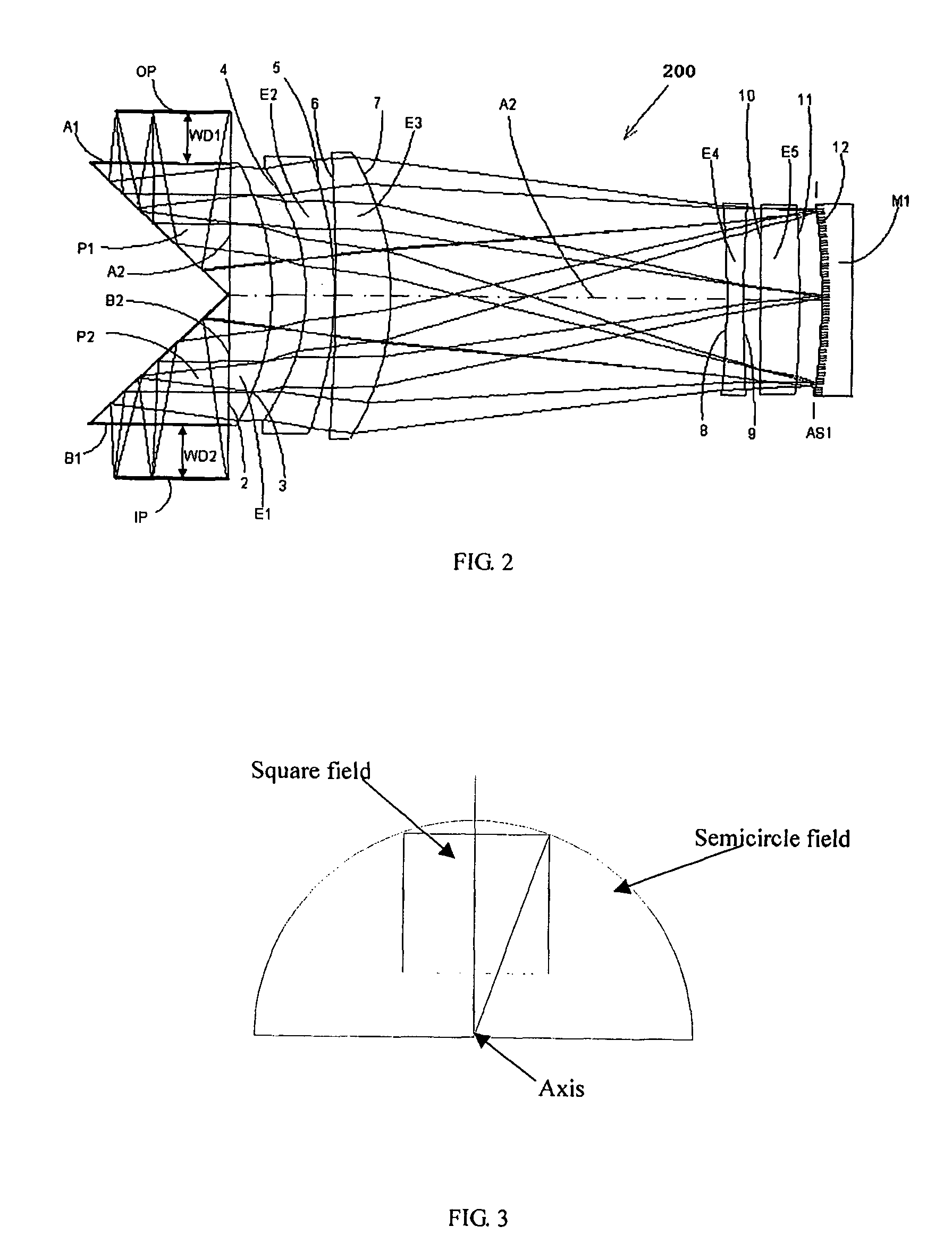
[0023]FIG. 2 is a schematic view of an example embodiment of a large-field unit-magnification projection optical system 200 of the present invention. The optical system 200 includes an axis A2, a concave spherical mirror M1 with an associated aperture stop AS1. The concave spherical mirror M1 has a concave surface 12.

[0024]Optical system 200 further includes a lens group with positive refractive power that includes a lens E5 adjacent to and spaced apart from mirror M1, a negative lens E4 adjacent to the lens E5, a positive lens E3 spaced apart from the negative lens E4, and a negative lens E2 adjacent from the positive lens E3.

[0025]The lens E5 is plano-convex with a surface 11 being convex and a surface 10 being flat.

[0026]The Lens E4 is negative double-concave with a surface 8 and a surface 9 faced to the mirror M1.

[0027]The positive lens E3 has a surface 6 being conc...


PUM


Abstract

The present invention discloses a large-field unit-magnification projection optical system. The optical system includes an optical axis, a spherical concave reflection mirror; a lens group with positive refracting power arranged adjacent the mirror with an air space therebetween. The lens group includes a first plano-convex lens, a negative meniscus lens adjacent the plano-convex lens, a positive lens adjacent the negative meniscus lens, a negative double-convex lens spaced apart far from the positive lens, and a second plano-convex lens. The optical system further includes a pair of prisms each having respective first and second surface. The second surfaces are arranged adjacent the flat surface of the plano-convex lens element on opposite sides of the optical axis and the first surfaces are arranged adjacent object planes and image planes, respectively. Each lens in the lens group and the pair of prisms provide chromatic aberration correction in a spectral region that contains at least g, h and i-line wavelengths. In this projection optical system, the object plane is parallel to the image plane.

Description

TECHNICAL FIELD[0001]The present invention relates to optical projection systems and in particular to a large-field unit-magnification projection optical system.BACKGROUND OF THE INVENTION[0002]At present, photolithography is widely employed in sub-micron resolution integrated circuit (IC) manufacturing. With an increasing degree in gold-bumping and other wafer-level IC packaging technologies, there has been an increasing demand for the projection optical system having a large depth of focus, a high throughput, and a relatively low (i.e., a few microns) resolution. Projection photolithography has been developed and applied gradually.[0003]The present invention described below is related to the optical system described in U.S. Pat. No. 6,879,383 (hereinafter, “the '383 patent”) issued on Apr. 12, 2005 to Mercado and assigned to Ultratech, Inc.[0004]FIG. 1 is a cross-sectional diagram of an example optical system 100 according to the '383 patent.[0005]The invention described in the '3...

Claims


Application Information

Patent Timeline
Patent Type & Authority Patents(United States)
IPC IPC(8): G02B9/60G02B17/00
CPCG03F7/70791G03F7/70225G02B17/08G02B13/26
Inventor LI, TIEJUNHUANG, LINGWEI, JUN
Owner SHANGHAI MICRO ELECTRONICS EQUIP (GRP) CO LTD
Why Eureka
Try Eureka