
System and method for low-density parity check (LDPC) code design

a code design and low-density parity technology, applied in the field of wireless communication, can solve the problems of affecting the quality of the communication channel over which the source and destination communicate, the inability to reliably transmit rates above the capacity, and the distortion of the messag

Inactive Publication Date: 2010-06-22
NEC CORP
View PDF1 Cites 6 Cited by
  • Summary
  • Abstract
  • Description
  • Claims
  • Application Information

AI Technical Summary

Benefits of technology

This approach enhances the design of LDPC codes for half-duplex relay channels by improving decoding performance and reliability in scenarios with varying SNRs, enabling more effective error detection and correction.

Problems solved by technology

Given a communication channel, there exists a number, called the capacity of the channel, such that reliable transmission is possible for rates arbitrarily close to the capacity, and reliable transmission is not possible for rates above the capacity.
Alternatively or additionally, the communication channel over which the source and destination communicate may be poor quality.
As a result, interference may be introduced in the communications between the source and the destination, which can result in distortion of the message.
Even while using a coding scheme, a destination may not be able to detect the transmitted message because of interference.
The design of rate compatible LDPC codes employing the conventional density evolution algorithm, however, typically considers extra constraints on the code ensembles due to the specific structure of rate compatible codes.
While the structure of LDPC codes for half-duplex relay networks are in part similar to rate compatible code structures, current design methods based on Guassian approximation of density are typically not directly applicable to the problem of half-duplex relay channel code design because of a variation of receive signal to noise ratios (SNRs) in different sub-blocks of one codeword.

Method used


Image

  • System and method for low-density parity check (LDPC) code design
  • System and method for low-density parity check (LDPC) code design
  • System and method for low-density parity check (LDPC) code design

Examples


Embodiment Construction

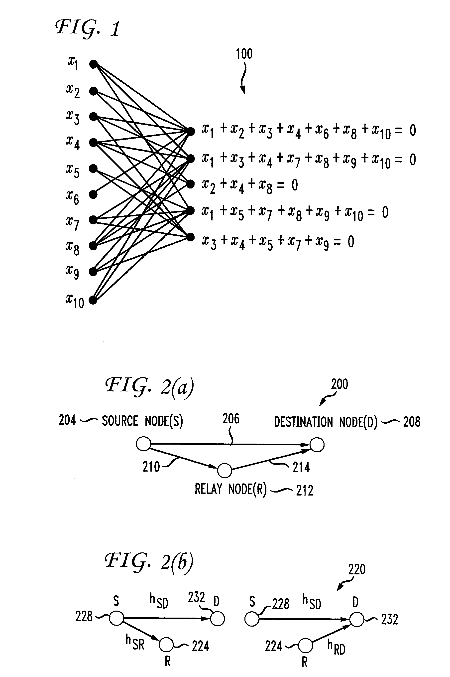
[0047]FIG. 2(a) shows full-duplex relay operations of a single relay system 200 during a single time slot. In particular, a source node, or source S, 204 communicates a message 206 to a destination node, or destination D, 208 during a time slot. The source 204 also communicates the message 210 to a relay node, or relay, 212. The relay 212 communicates the same message (shown with arrow 214) to the destination 208. Because the system 200 is a full-duplex relay system, the relay 212 can receive the message 210 from the source 204 and simultaneously transmit the message 214 to the destination 208. The source 204, relay 212, and destination 208 can be wireless terminals in a wireless network.

[0048]FIG. 2(b) shows half-duplex relay operations of a single relay system 220 during two consecutive time slots. Specifically, the left side of FIG. 2(b) shows the operations within the odd time slot and the right side of FIG. 2(b) shows the operation within the even time slot. During the odd time...


PUM


Abstract

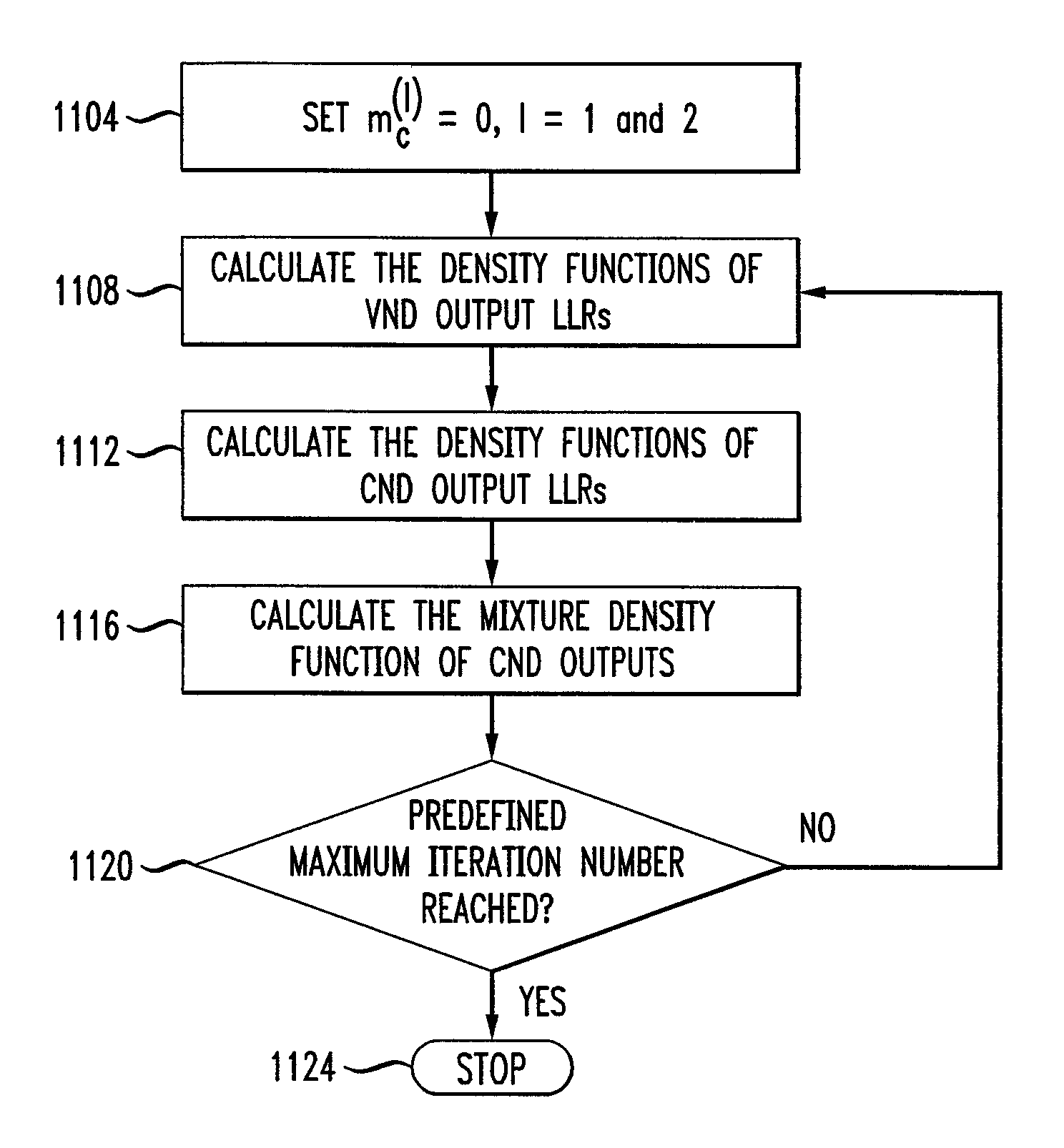
Disclosed is a density evolution algorithm based on a refined definition of node and edge densities for different parts of the code. In particular, density functions ƒV(1)(i) and ƒV(2)(i) of the output edges of the variable nodes with degree i within different codeword regions w1 and we, respectively, are defined and then calculated. Further, density functions ƒC(1)(j) and ƒC(2)(j) of the output edges for check nodes with degree j within codeword regions w1 and we, respectively, are defined and then calculated. Mixture density functions of output check edges connecting variable nodes in the first codeword region and the second codeword region are then calculated to determine an LDPC code design.

Description

[0001]This application claims the benefit of U.S. Provisional Application No. 60 / 730,715 filed Oct. 27, 2005, which is incorporated herein by reference.BACKGROUND OF THE INVENTION[0002]The present invention relates generally to wireless communications, and more particularly to low-density parity check code design.[0003]In wireless communications, a transmitter typically transmits information to a receiver over a communication channel. Statistically, a communication channel can be defined as a triple consisting of an input alphabet, an output alphabet, and for each pair (i,o) of input and output elements of each alphabet, a transition probability p(i,o). The transition probability is the probability that the receiver receives the symbol o given that the transmitter transmitted symbol i over the channel.[0004]Given a communication channel, there exists a number, called the capacity of the channel, such that reliable transmission is possible for rates arbitrarily close to the capacity,...

Claims


Application Information

Patent Timeline
Patent Type & Authority Patents(United States)
IPC IPC(8): H03M13/00
CPCH03M13/033H03M13/6393H03M13/1105
Inventor LI, CHUXIANGYUE, GUOSENKHOJASTEPOUR, MOHAMMAD A.WANG, XIAODONGMADIHIAN, MOHAMMAD
Owner NEC CORP
Learn More