Display device

a technology of display device and screen, which is applied in the direction of television system, electric apparatus casing/cabinet/drawer, instruments, etc., can solve the problems of affecting the operation and affecting the display effect of the display device, so as to achieve the effect of optimizing the display height, reducing the labor of the user in changing the screen orientation, and ensuring the balance of the rotation operation

Inactive Publication Date: 2010-06-15
FUJITSU LTD
View PDF11 Cites 9 Cited by
  • Summary
  • Abstract
  • Description
  • Claims
  • Application Information

AI Technical Summary

Benefits of technology

[0008]It is therefore an object of the present invention to provide a display device for which the rotational center matches the screen center, which is a display device that places the screen position in a suitable position with respect to the user when the screen is rotated. A display device that does not require re-attachment of the accessories even when the screen is rotated is preferable.
[0013]According to the present invention, when the orientation of the screen is changed to vertical or horizontal, the user is able to optimally adjust the height of the screen whose orientation has been changed simply by performing a screen rotation operation in which the center of the screen is taken as the rotational center. Thus, the user is able to effect a change in screen orientation and a height adjustment by means of a single operation and the labor of the user in changing the screen orientation is lightened.
[0014]Because the rotational center is the center of the screen, the rotational operation can be well balanced and a weighting bias can be prevented. Excess member damage is also prevented.
[0015]Further, it is sufficient for the user to rotate the screen to the right or left to change the orientation of the screen and product damage that is induced by limiting the rotation of the screen to the one direction can be prevented. Further, this means a superior design for the user (user-friendly).
[0016]In addition, when an operation key or the like for adjusting the speaker or screen is attached to the display device, accessories are disposed in suitable positions on the left and right of the display device irrespective of whether the screen is oriented vertically or horizontally. Thus, the work of re-attaching the accessories by the user is unnecessary even when the orientation of the screen is changed and the labor by the user that accompanies changing the screen orientation is lightened.

Problems solved by technology

However, in the prior art, which relates to a display device that allows the orientation of the screen to be changed, the rotational center does not necessarily match the screen center, the rotation operation lacks balance, and weight is placed on inclined parts.
Therefore, wear damage to members which are used as the rotation mechanism and the support mechanism for supporting the screen is sometimes premature.
When members wear out due to periods of long usage, in cases where the user removes the hand supporting the rotation operation by mistake, the display device is damaged through contact with the floor or desk as a result of the screen turning by itself due to the eccentricity of the rotational center and the possibility exists that the user will be injured.
Furthermore, in the prior art, there have been instances where the direction of rotation is one preset direction and, when the user applies an excessive force by mistake in the direction in which the screen is unable to rotate, the result has been damage to the rotational mechanism.
Thus, the mismatch between the rotational center and screen center and the asymmetry such that rotation is possible in only one direction are not user-friendly and bring about the result of reducing the user convenience of the product.
Although there are also products that allow accessories to be detached from the screen, there is work required in re-attaching the accessories at suitable points after the orientation of the screen is changed, which is troublesome.

Method used


Image

  • Display device
  • Display device
  • Display device

Examples


first embodiment

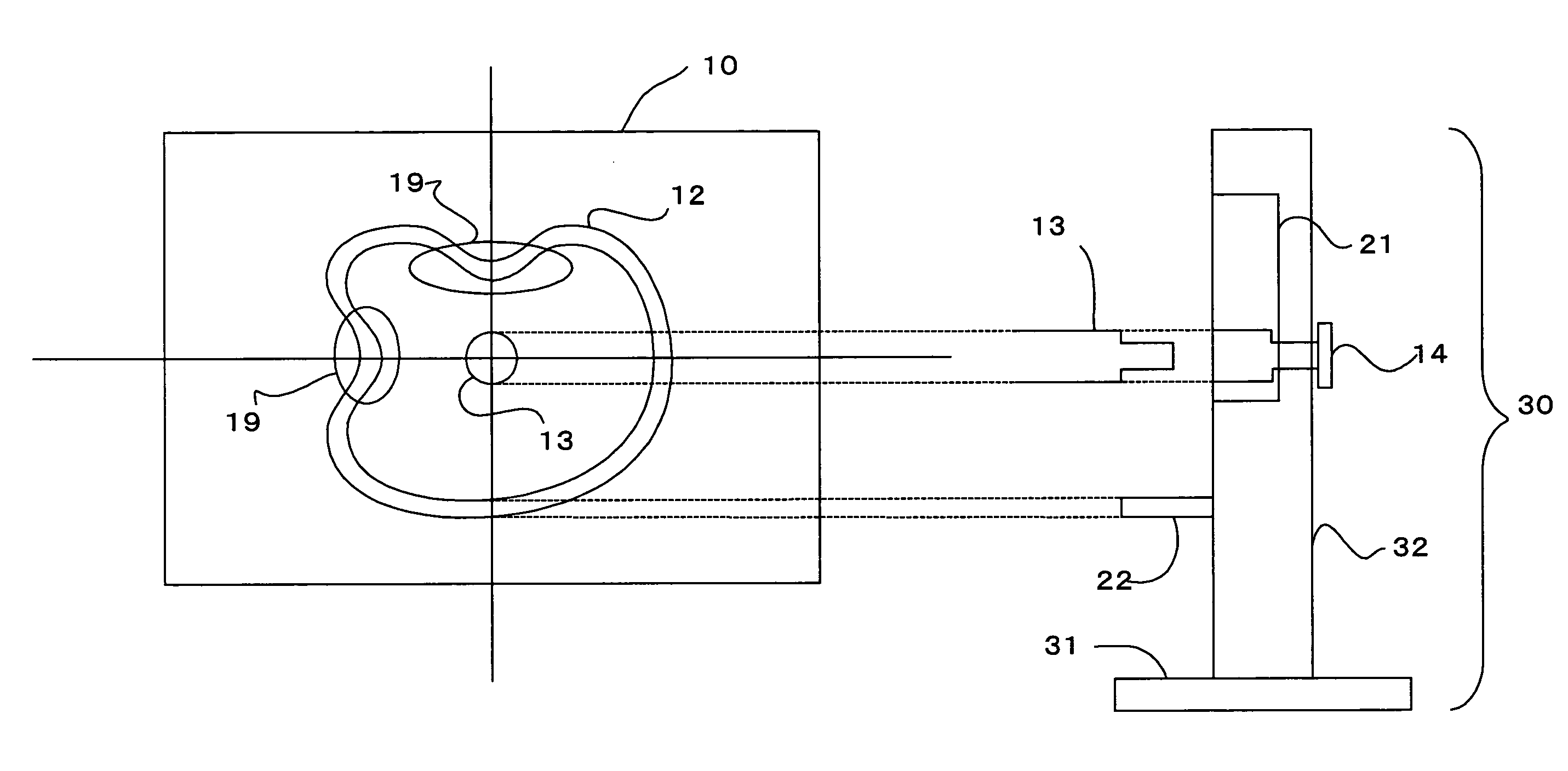
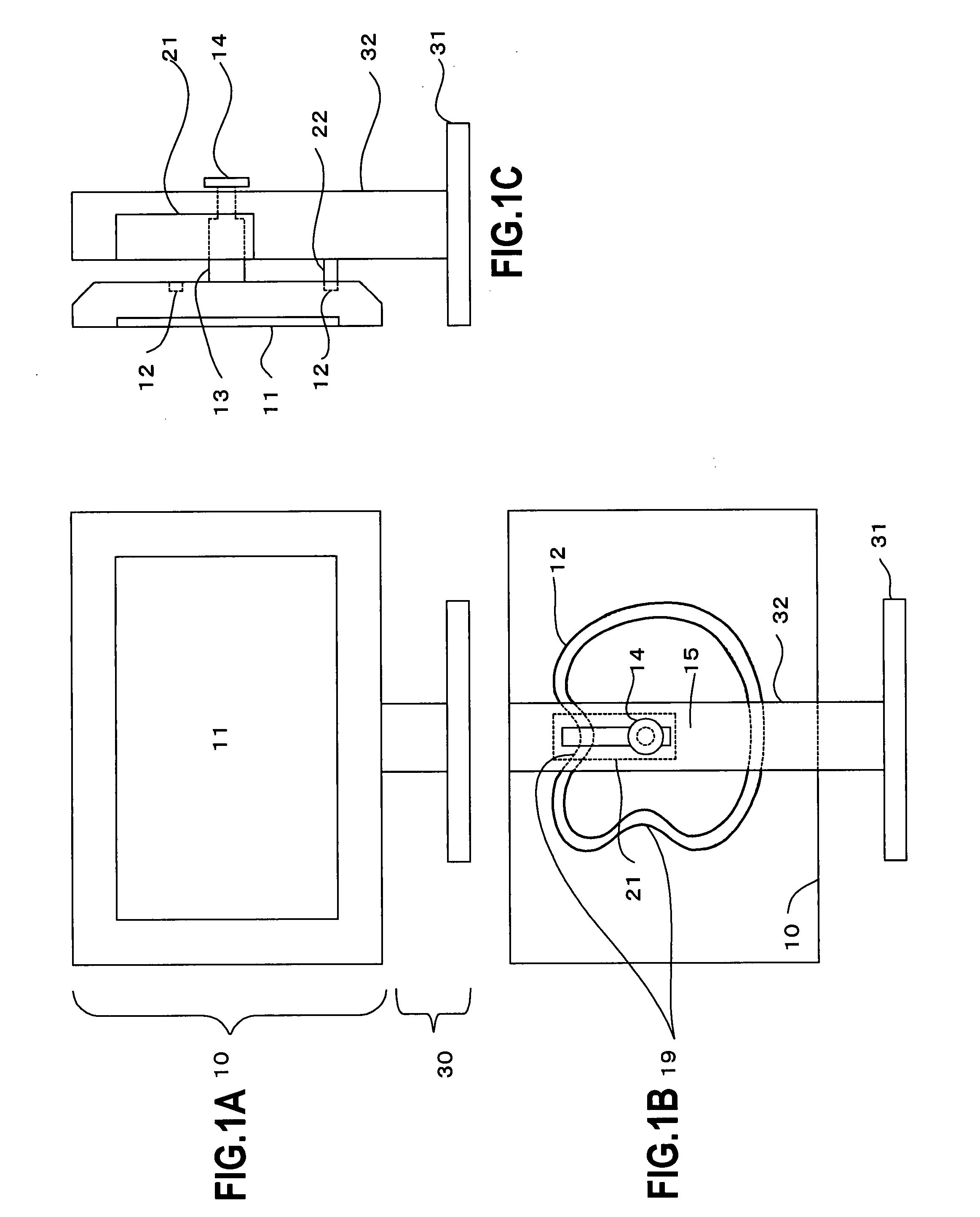
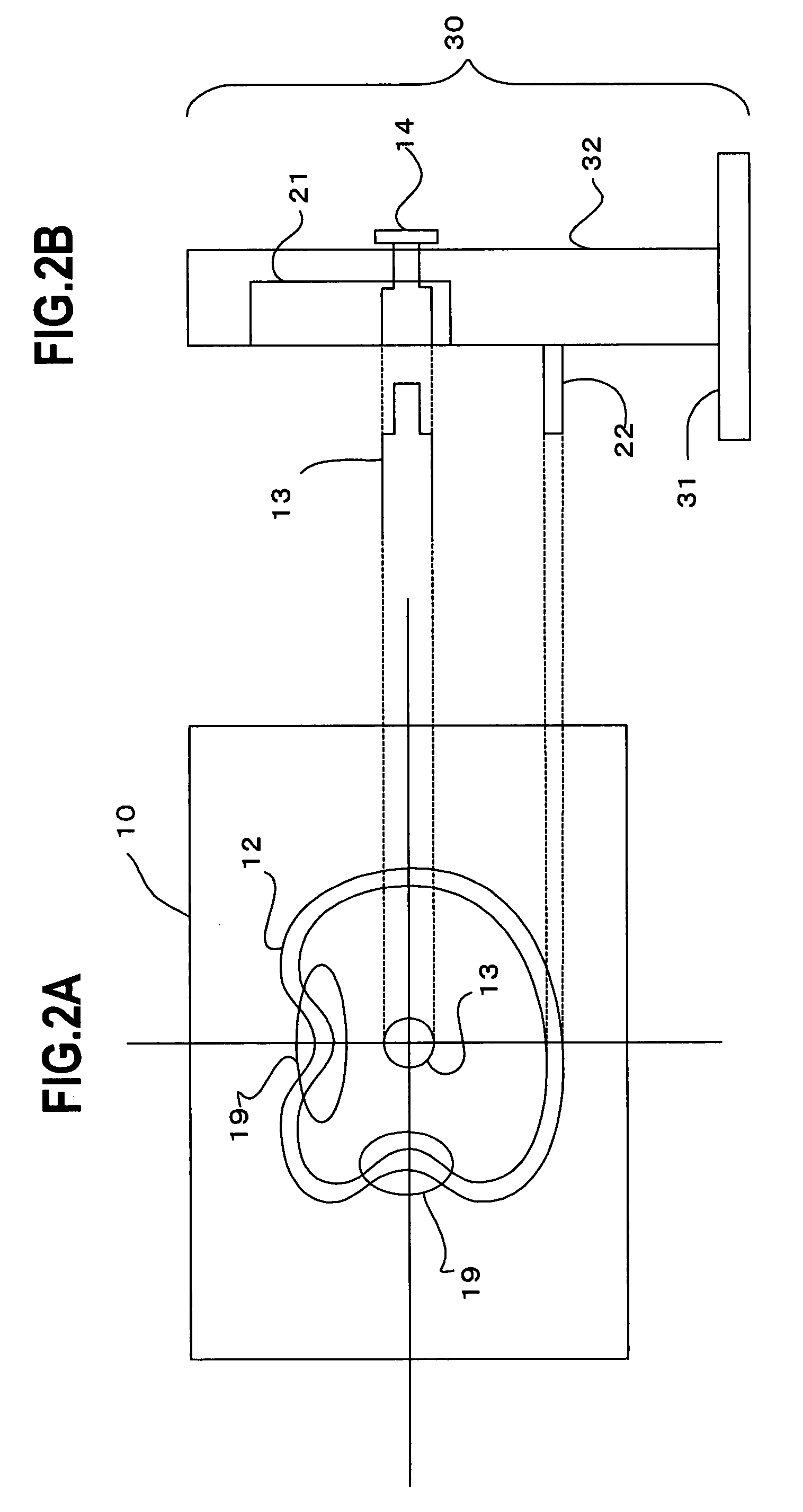
[0030]FIG. 1 illustrates the display device of the present invention. FIG. 1A is a front view of the display device; FIG. 1B is a rear view of the display device; and FIG. 1C is a right-sided view of the display device. The display device is constituted by the display section 10 that comprises a monitor 11, which is a substantially rectangular-shaped display screen that displays information, and stand 30 which supports the display section 10.

[0031]With reference to FIG. 1B, a cylindrical fixed pin 13 that is perpendicular to the display section 10 is fixed to the display section 10 on the rear face of the display section 10. With reference to FIG. 1C, the fixed pin 13 has a dual-stage structure with a small diameter at a midway point and the tip of the fixed pin 13 penetrates the stand 30 and has abroad fixed member 14 attached thereto. Thus, the display section 10 does not fall forward (left direction in FIG. 1C).

[0032]With reference to FIG. 1C, the rear face of the display section...

second embodiment

[0073]In the display device of the second embodiment, the cam 16 that forms the annular track is provided on the rear face of the display section 10 and the pulley 23 that contacts the cam 16 is provided on the rear face plate 32 of the stand. The pulley 23 is an abutment member that contacts the cam 16 and supports the display section 10. The cam 16 has a predetermined thickness and the outer circumference thereof is followed by the pulley 23. The outer circumference forms an annular track.

[0074]When the display section 10 is rotated, the pulley 23 follows the outer circumference of the cam 16 and the display section 10 is displaced accordingly. This means that, viewed in relative terms, the pulley 23 is guided by the cam 16 and moves along the annular track formed by the outer circumference of the cam 16. Here, because the pulley 23 is fixed to the arm 33, the fixed pin 13 that is fixed to the display section 10 moves along the linear groove 21 in accordance with the distance betw...


PUM


Abstract

A conventional display device is constituted such that, when the display section is rotated to change the orientation thereof, the center of rotation and the center of the display section do not coincide, whereby the rotation operation lacks balance. Hence, the present invention provides a display device comprising a guide mechanism that comprises an annular track that rotates as the display section rotates and a guided member that is fixed to contact the annular track contained in the guide mechanism. By providing the annular track with recesses for fixing the position of the display section when the orientation of the display section is vertical or horizontal, the center of rotation and the center of the display section coincide, and also the screen height following the rotation can be optimized as a result of the rotation operation.

Description

CROSS REFERENCE TO RELATED APPLICATIONS[0001]This application is a continuation of International Application No. PCT / JP2004 / 13346, filed on Sep. 14, 2004, now pending, herein incorporated by reference.TECHNICAL FIELD[0002]The present invention relates to a display device and, more particularly, to a display device in which the height of the screen can be varied in conjunction with the rotation of the screen.BACKGROUND ART[0003]Display devices and, in particular, liquid crystal display devices, are used on many occasions as display devices of PCs (Personal Computers) because they are small, lightweight and offer space savings. Due to the diversity of the application programs that are run on PCs, there are instances where it is appropriate to use the long side of the screen vertically and parallel to the upright direction rather than using the screen, which has a substantially rectangular shape, horizontally. For example, when content on the Internet is viewed by means of a browser, b...

Claims


Application Information

Patent Timeline
Patent Type & Authority Patents(United States)
IPC IPC(8): G06F1/16
CPCF16M11/06F16M11/105F16M13/02G06F1/1601F16M11/22G06F2200/1612
Inventor OSHIMA, USHIO
Owner FUJITSU LTD
Why Eureka
Try Eureka