
Apparatus for capping bottles and a method for realising the cap

a technology for capping apparatuses and bottles, applied in the field of capping apparatuses for bottles, to achieve the effect of simple realization

Active Publication Date: 2010-06-15
MARCHESINI GROUP SPA
View PDF9 Cites 9 Cited by
  • Summary
  • Abstract
  • Description
  • Claims
  • Application Information

AI Technical Summary

Benefits of technology

The present invention provides a capping apparatus for bottles that includes a single supply channel, requires no intervention when the machine it is installed on is changed, includes organs for hooking and inserting caps into bottles, and is adaptable to both intermittent and continuous machines. The invention also provides a new and simple method for capping bottles that can be easily realized and adapted to different machines. The apparatus includes gripping devices for bottles, a channel for supplying caps, and a pick-up organ for extracting and positioning caps in bottles. The technical effects of the invention include improved efficiency, flexibility, and adaptability for different machines and methods.

Problems solved by technology

To cap a group of n bottles there must be n supply channels, n receiving and positioning arms and the same number of extractor organs and pusher organs, with all the drawbacks that derive from the functional complexity of the apparatus and the maintenance of the cap positioning and bottle closing devices.

Method used


Image

  • Apparatus for capping bottles and a method for realising the cap
  • Apparatus for capping bottles and a method for realising the cap
  • Apparatus for capping bottles and a method for realising the cap

Examples


Embodiment Construction

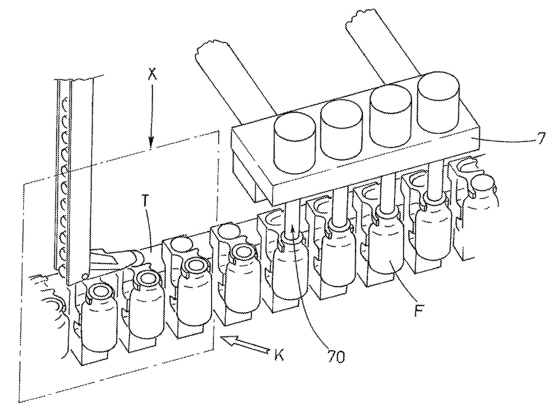
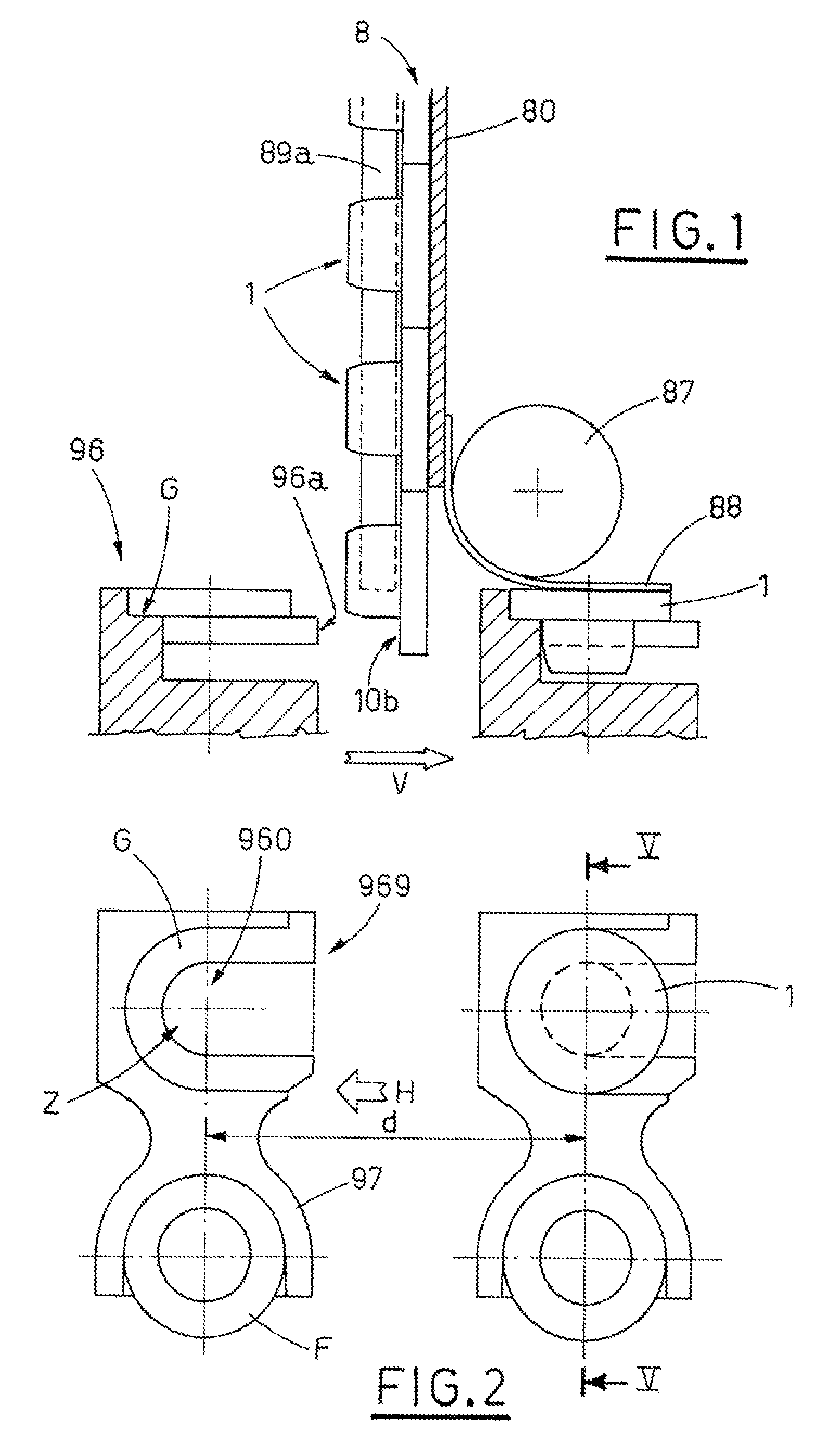
[0024]With reference to the figures of the drawings, T denotes a transporter to which gripping devices 9 for the bottles F containing products, for example liquids, granular and / or powder products, are externally blocked according to an interaxis d.

[0025]Each gripping device 9, as illustrated in FIGS. 2, 5A, 5B is constituted, for example (see EP 0626770.4 belonging to the present applicant) by: a vertical portion 90, constrained to the external part Te of the transporter T; a support base 99, which extends external-wise perpendicularly from the vertical portion 90, on which the bottom of a bottle F partially rests; an intermediate striker 98 for the bottle F, parallel to the support base 99 which partially embraces the bottle F; a sort of pliers 97, which extend towards the outside of the transporter T, perpendicularly from the vertical portion 90, to which the neck of the bottle F is hooked.

[0026]To guide the bottles F hooked to the gripping devices 9, as illustrated in FIGS. 5A, ...


PUM


Abstract

An apparatus for capping bottles, comprising: gripping devices for bottles containing products, constrained to a transporter, each of which gripping devices exhibits on a side thereof a gripping means of a corresponding bottle, and on an opposite side thereof hooking-receiving-stabilizing organ of a cap; at least a channel for supplying caps, arranged superiorly of the transporter upstream of a capping zone overlying the hooking-receiving-stabilizing organs transiting below the channel, into which a row of caps is conveyed, a head cap of the row of caps being held elastically by a lower end of the supply channel in order to position an internal surface of a relative head such as to intercept a front head (96a) of an underlying hooking-receiving-stabilizing organ in order to enable the head cap, in combination with the advancing of the transporter and with the striking and guiding action exerted by the supply channel, to disengage from the supply channel in order to locate in the corresponding hooking-receiving-stabilizing organ, with the relative body facing downwards; at least a pick-up organ, located in the capping zone, operating in phase relation with a corresponding hooking-receiving-stabilizing organ, with the body thereof facing downwards; at least a pick-up organ destined to hook and extract the cap present therein, and to position the cap axially in an inlet mouth of the corresponding bottle supported by the gripping device flanking the hooking-receiving-stabilizing organ, in order to perform insertion of the body of the cap in the mouth of the bottle in order to close the bottle.

Description

BACKGROUND OF THE INVENTION[0001]The invention relates to the technical sector of capping apparatus for bottles.[0002]The prior art describes bottles which are hooked by gripping means, associated to a transporter which enables the advancing of the bottles from a filling station, in which they are filled with products, for example liquids, granular and / or powder materials, towards a station in which capping apparatus are provided.[0003]A known capping apparatus is constituted by: supply channels, arranged inclined transversally to the advancement direction of the transporter and, therefore, to the bottles, to each of which caps are conveyed to identify a row, where the leading cap strikes against a striker such as to stabilize a position thereof above an extractor, with the body of the cap facing upwards; a receiving and positioning arm, hinged at an end thereof to a base and exhibiting at another end thereof a through-hole for receiving.[0004]The receiving and positioning arm takes...

Claims


Application Information

Patent Timeline
Patent Type & Authority Patents(United States)
IPC IPC(8): B65B7/28
CPCB67B1/04B67B1/005
Inventor MONTI, GIUSEPPE
Owner MARCHESINI GROUP SPA
Learn More