
Semiconductor device and method of cutting electrical fuse

a technology of electrical fuse and semiconductor device, which is applied in the direction of discharge tube/lamp details, sparking plugs, instruments, etc., can solve the problems of increasing the number of cutting processing times, the inability to accurately decide whether the fuse that should have been cut is cut, and the configuration of the fuse is complicated. achieve the effect of simple method and higher decision accuracy

Active Publication Date: 2010-06-01
RENESAS ELECTRONICS CORP
View PDF11 Cites 7 Cited by
  • Summary
  • Abstract
  • Description
  • Claims
  • Application Information

AI Technical Summary

Benefits of technology

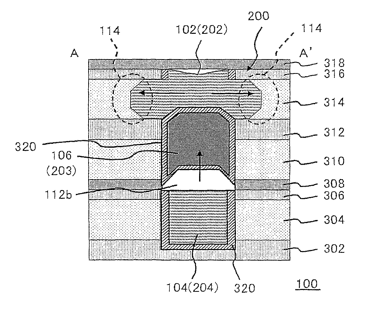
[0015]The present inventor has found a novel technique for cutting electric fuses, in which a constitution of an electric fuse or a manner for applying an electric voltage to an electric fuse is suitably controlled, so that a part of an electric conductor that constitutes an electric fuse is forced to be flowed toward outside of the electric fuse leading to losing a balance between a migration and a supply of the electric conductor material, thereby forming a larger cut part in other part when the electric fuse is cut or broken. This allows maintaining an improved condition in cutting or breaking of a cut electric fuse. According to the present invention, the first cutting target region and the second cutting target region are cut or broken using such a cutting mechanism.
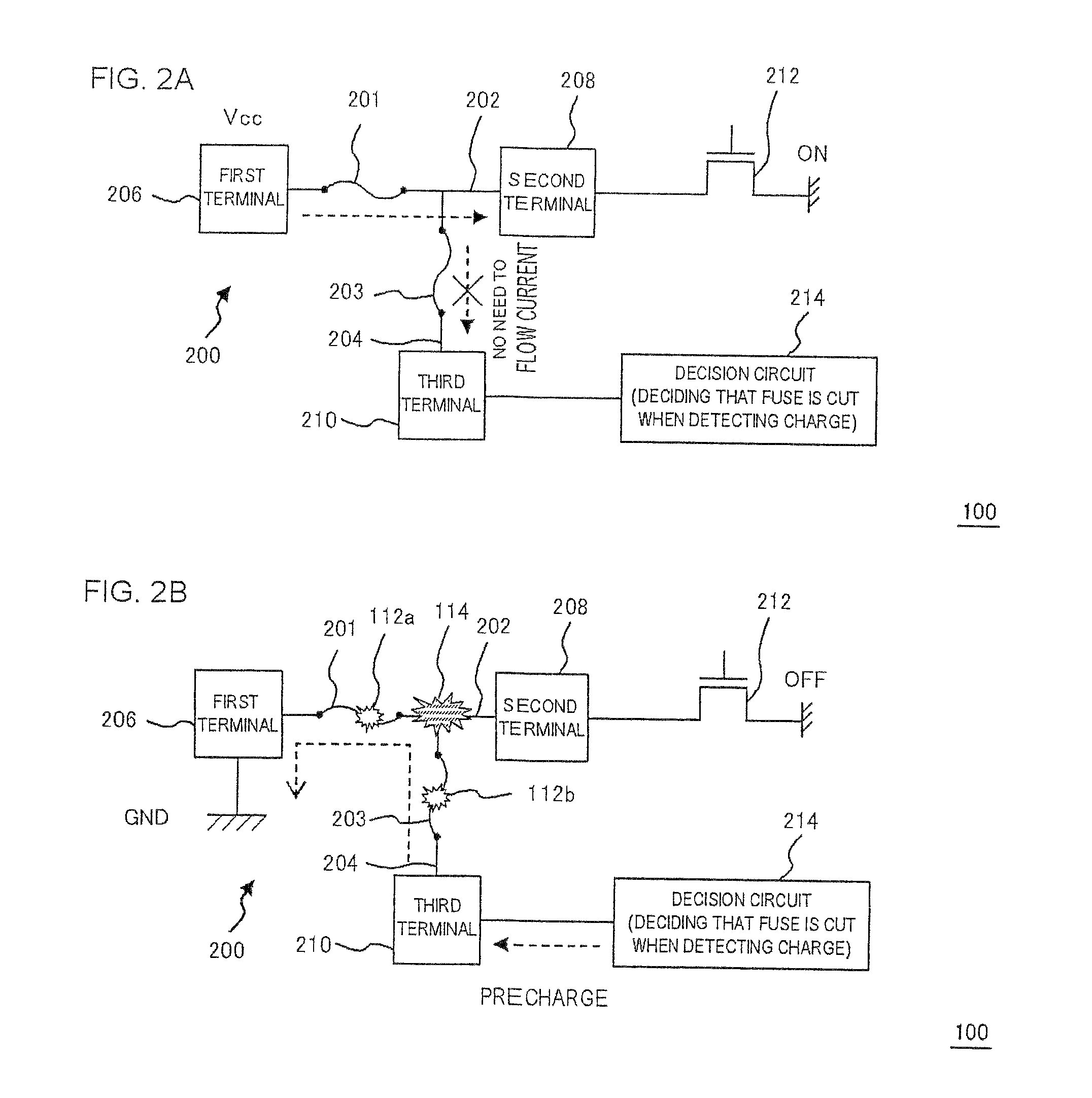
[0017]The constitution of the present invention allows the two broken point to be formed in one electrical fuse by conducting one processing. It is thereby possible to decide whether the electrical fuse is cut based on cutting condition of the two broken points. Namely, the electrical fuse may be configured so that the first cutting target region is connected to a decision circuit deciding whether the electrical fuse is cut, via the second cutting target region, the decision circuit. It is thereby possible to decide that the electrical fuse is cut when either the first cutting target region or the second cutting target region is cut, and the deciding accuracy can be higher. This allows maintaining an improved condition in cutting or breaking of a cut electric fuse. Here, the second conductor is branched from and connected to the first conductor in a portion different from the first cutting target region.
[0023]According to the present invention, deciding accuracy of the electrical fuse can be higher by a simple method.

Problems solved by technology

When the electrical fuse is insufficiently cut or constituent materials of the fuse migrates and the fuse is connected again after the fuse is cut once, it is impossible to accurately decide whether the fuse that should have been cut is cut.
As a result, these may cause a problem that the number of times of cutting processing increases and the configuration of the fuse is complicated.

Method used


Image

  • Semiconductor device and method of cutting electrical fuse
  • Semiconductor device and method of cutting electrical fuse
  • Semiconductor device and method of cutting electrical fuse

Examples


Embodiment Construction

[0033]The invention will be now described herein with reference to illustrative embodiments. Those skilled in the art will recognize that many alternative embodiments can be accomplished using the teachings of the present invention and that the invention is not limited to the embodiments illustrated for explanatory purposed.

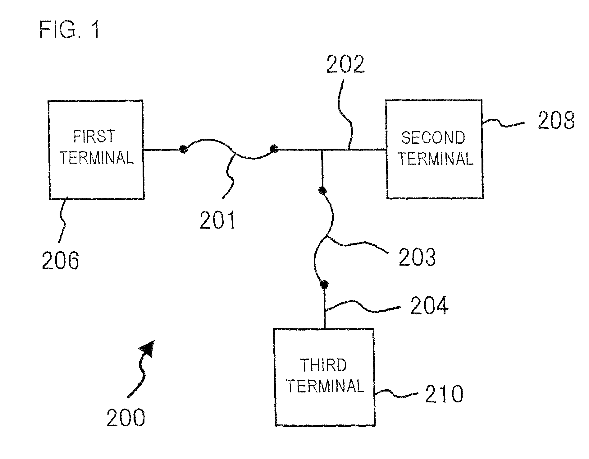
[0034]FIG. 1 is a layout view showing a configuration of an electrical fuse 200 according to an embodiment of the present invention.

[0035]The electrical fuse 200 includes a first conductor 202 including a first cutting target region 201, and a second conductor 204 formed to be branched from the first conductor 202 and including a second cutting target region 203. Although not shown in the drawings, the electrical fuse 200 is formed on a semiconductor substrate and formed in insulating films multiple-layered on the semiconductor substrate. In the present embodiment, each of the first conductor 202 and the second conductor 204 that constitute the electrical fuse 20...


PUM


Abstract

A semiconductor device includes a semiconductor substrate, and an electrical fuse including a first conductor including a first cutting target region, and a second conductor branched from the first conductor and connected to the first conductor and including a second cutting target region, which are formed on the semiconductor substrate, wherein a flowing-out region is formed of the first conductor flowing toward outside between the first cutting target region and the second cutting target region in a condition of cutting the electrical fuse.

Description

[0001]This application is based on Japanese Patent application NO. 2006-153510, the content of which is incorporated hereinto by reference.BACKGROUND[0002]1. Technical Field[0003]The present invention relates to a semiconductor device and a method of cutting an electrical fuse. More specifically, the present invention relates to a semiconductor device including an electrical fuse and a method of cutting an electrical fuse.[0004]2. Related Art[0005]A technology is conventionally known, in which a fuse is mounted in a semiconductor device, and the electric fuse is broken, so that a value of a resistor employed in the semiconductor device is suitably adjusted, or a failure element is separated and replaced into a normal element.[0006]Typical manner for cutting a fuse includes cutting a fuse by irradiating a laser beam in a portion of the fuse and cutting a fuse by applying an electric current.[0007]U.S. Pat. No. 4,064,493 discloses an electric fuse, which is capable of being broken by ...

Claims


Application Information

Patent Timeline
Patent Type & Authority Patents(United States)
IPC IPC(8): H01L29/00
CPCH01L23/5256H01L2924/0002H01L2924/00
Inventor UEDA, TAKEHIRO
Owner RENESAS ELECTRONICS CORP
Learn More