
Light illumination device

a technology of led illumination and light, which is applied in the direction of semiconductor devices, light sources, lighting and heating apparatus, etc., can solve the problems of low frequency of illumination ripple, increase manufacturing cost, and large size of illumination ripple, and achieve excellent illumination quality and reduce the effect of light flicker

Inactive Publication Date: 2010-06-01
STANLEY ELECTRIC CO LTD
View PDF10 Cites 7 Cited by
  • Summary
  • Abstract
  • Description
  • Claims
  • Application Information

AI Technical Summary

Benefits of technology

[0014]Accordingly, the presently disclosed subject matter has been devised in view of the foregoing and other problems and considerations. One of them many purposes of the presently disclosed subject matter is to provide an LED illumination device that includes a plurality of LEDs and is driven by directly applying a voltage from a commercial power source. In the LED illumination device, flicker effect and recognizable variations in plane luminance distribution can be reduced without providing rectification means inside the device. In addition, the device is excellent in illumination quality and is therefore should be easily marketable.
[0023]Hence, an LED illumination device can be realized which can be driven directly by a commercial power supply although the device does not have rectification means thereinside. Furthermore, the LED illumination device has excellent illumination quality which is obtained by reducing the light flicker effect that is typically due to a commercial frequency and recognizable variations in plane luminance distribution when the device is on.

Problems solved by technology

Therefore, the device becomes large, and the manufacturing cost increases.
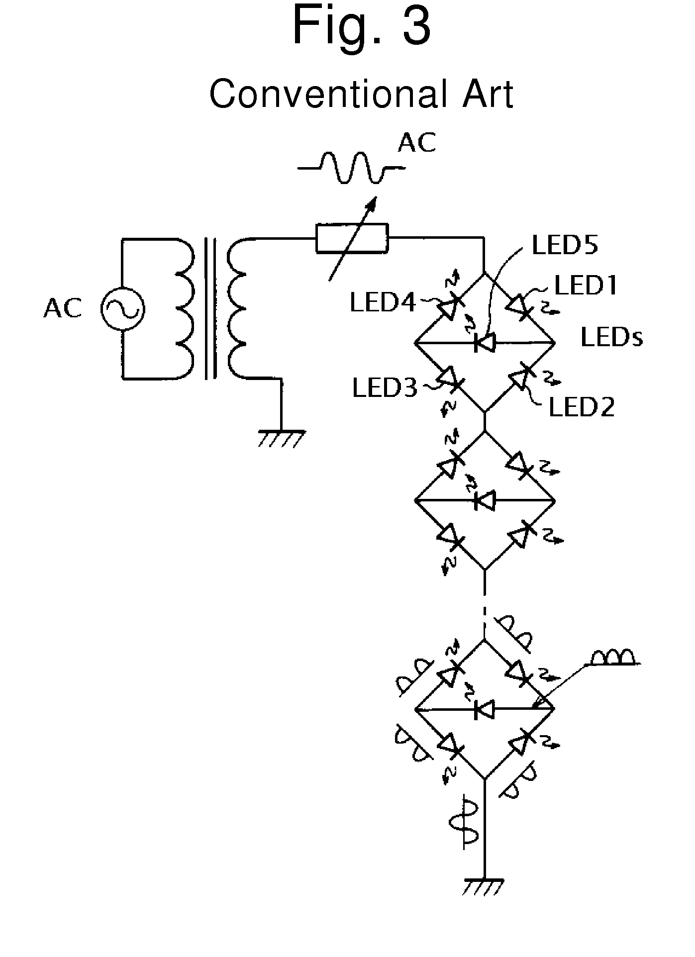
However, in LEDs driven by a half-wave rectified voltage from a commercial power supply, the frequency of illumination ripple may be low.
Therefore, a flicker effect can be recognized by normal human eyes, and thus a problem exists in that the LED illumination device lacks illumination quality and therefore lacks marketability.
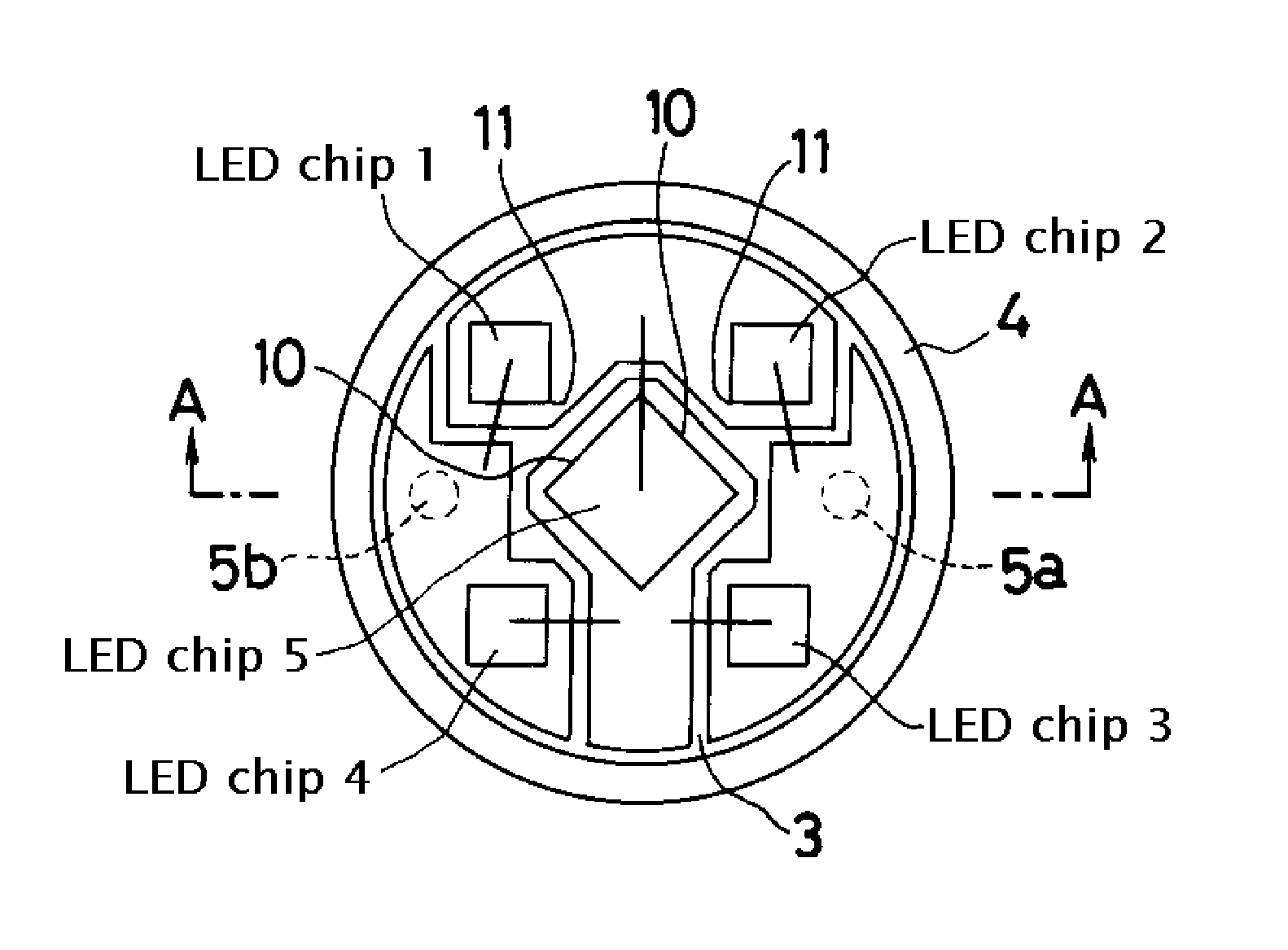
Moreover, the placement range for the five LED chips can be limited, and the LED chips can be sealed with a fluorescent (or other wavelength conversion) material.

Method used


Image

  • Light illumination device
  • Light illumination device
  • Light illumination device

Examples


Embodiment Construction

[0035]In an LED illumination device driven directly by a commercial power supply, an improvement in illumination quality and possibly marketability can possibly be realized by reducing a flicker effect by optimizing the circuit configuration and installation method of LED chips.

[0036]Hereinafter, exemplary embodiments of the presently disclosed subject matter will be described in detail with reference to FIGS. 4 to 10. The same or similar parts are designated by the same numerals. The embodiments described hereinafter are examples of the presently disclosed subject matter, and thus include various technical features and characteristics. However, the scope of the disclosed subject matter is not limited to the described embodiments.

[0037]FIG. 4 is a plan view of one example of an LED illumination device made in accordance with principles of the disclosed subject matter, and FIG. 5 is a cross-sectional view taken along line A-A of FIG. 4. Furthermore, FIG. 6 is a circuit diagram, and F...


PUM


Abstract

An LED illumination device can include a bridge connection circuit that includes five LED chips. The LED chips can be installed such that four LED chips, through which half-wave rectified current flows, are disposed in a generally cross-shaped opposed arrangement with the remaining LED chip interposed therebetween. The remaining LED chip can also have a full-wave rectified current flowing therethrough. Half-wave rectified currents having phases shifted by 180° (half the period) can flow through respective LED chips installed at a generally right angle. The placement range for the five LED chips can be limited, and the LED chips can be sealed with a wavelength conversion material.

Description

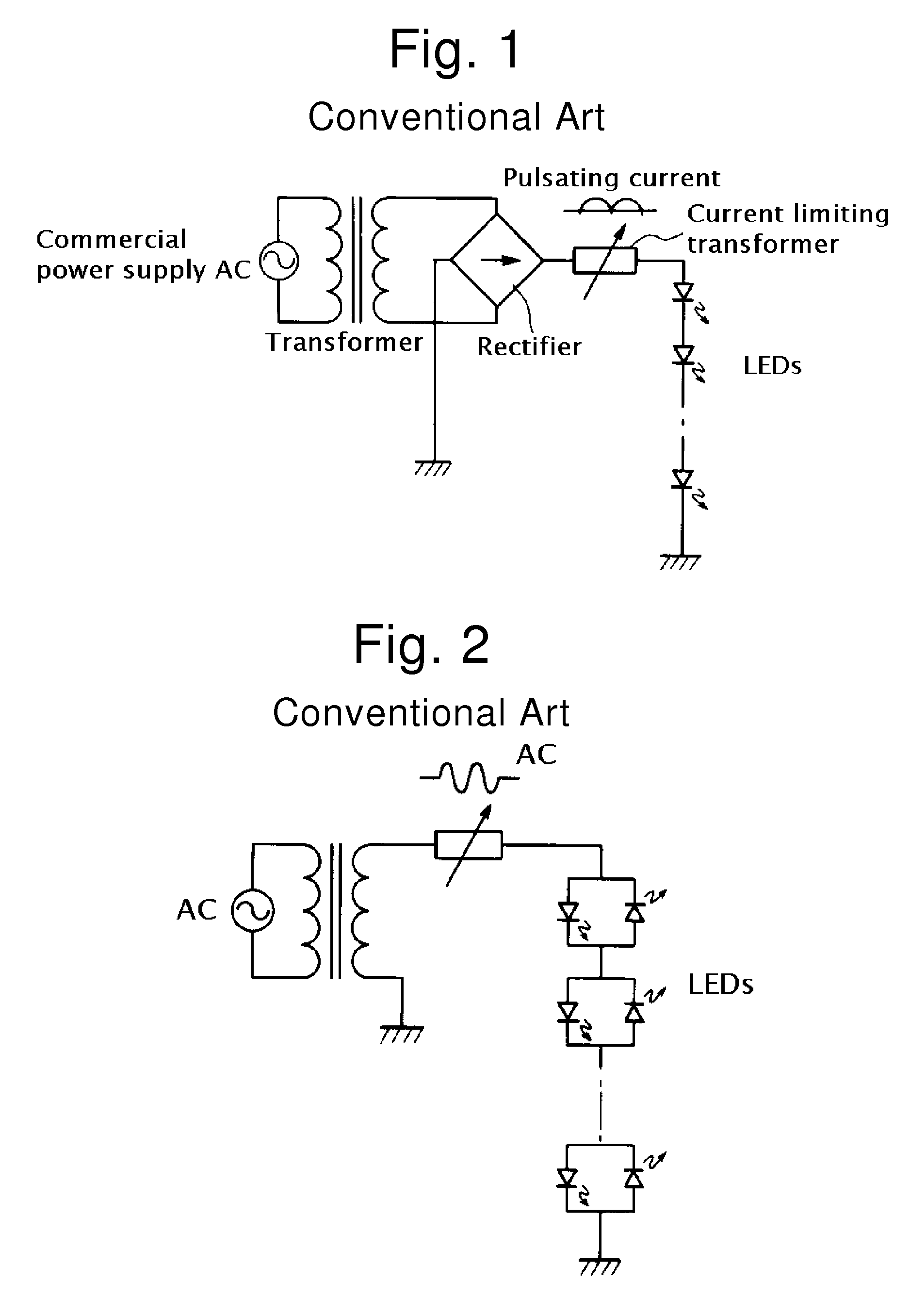
[0001]This application claims the priority benefit under 35 U.S.C. §119 of Japanese Patent Application No. 2005-314764 filed on Oct. 28, 2005, which is hereby incorporated in its entirety by reference.TECHNICAL FIELD[0002]The disclosed subject matter relates to an LED illumination device, and in particular to an LED illumination device which is driven directly by a commercial power supply.RELATED ART[0003]Examples of conventional methods for driving an LED illumination device include: (1) a method in which the device is driven by directly applying a DC voltage from a DC power supply such as a dry cell or a battery; (2) a method in which the device is driven by applying a DC voltage obtained by converting an AC voltage from an AC power supply, such as a commercial power supply, through the use of a constant voltage power supply; and (3) a method in which the device is driven by applying an AC voltage as is from an AC power supply, such as a commercial power supply, without conversion...

Claims


Application Information

Patent Timeline
Patent Type & Authority Patents(United States)
IPC IPC(8): H01L51/52H01L33/50H01L33/62
CPCF21K9/00H01L2224/48091H01L2924/00014
Inventor TAKIKAWA, HIROSHI
Owner STANLEY ELECTRIC CO LTD
Learn More