Controller and control method of vehicle

a technology of control device and control method, which is applied in the direction of machines/engines, engine components, mechanical equipment, etc., can solve the problems of inability to easily increase the amount of inlet air, the torque cannot be easily increased, and the driver can experience discomfort, so as to reduce the discomfort

Inactive Publication Date: 2010-06-01
TOYOTA JIDOSHA KK
View PDF7 Cites 1 Cited by
  • Summary
  • Abstract
  • Description
  • Claims
  • Application Information

AI Technical Summary

Benefits of technology

[0009]The invention provides a controller of a vehicle that reduces the discomfort that may be caused to a driver during a shift of an automatic transmission.
[0011]According to the controller of the vehicle in the first aspect of the invention, when the automatic transmission upshifts, the power source is controlled so that the torque-boost control of the power source is performed during the torque phase of the upshift. The torque-boost amount in the torque-boost control during the torque phase is set on the basis of the driver requested output amount (e.g., the driver requested torque or the accelerator operation amount). The torque-boost amount is set so that the torque-boost amount increases as the requested output amount increases, until the requested output amount exceeds a predetermined value. When the requested output amount exceeds the predetermined value, the torque-boost amount decreases even as the requested output amount continues to increase, and a torque obtained by adding the torque-boost amount to the requested torque corresponding to the requested output amount increases as the requested output amount increases. Therefore, when the driver requested output amount is small, so that the torque-boost can be sufficiently carried out, the torque-boost amount can be made larger the larger the requested output amount is. As there approaches a state in which the driver requested output amount is large so that the torque-boost cannot be sufficiently carried out, the torque-boost amount is gradually decreased. During this time, as the requested output amount increases, the torque obtained by adding the torque-boost amount to the requested torque that corresponds to the requested output amount increases. Therefore, it is possible to output a torque that corresponds to the driver requested output amount while restraining sudden changes in the control mode, such as a sudden change in which the torque-boost control of the engine suddenly ceases. As a result, it is possible to provide a controller of a vehicle that is able to reduce the discomfort that may be caused to the driver during a shift of the automatic transmission.
[0013]According to this construction, in the torque-boost control, the power source is controlled so that the torque is increased by the requested torque-boost amount. The requested torque-boost amount is set so as to gradually increase to the torque-boost amount during the torque phase of the upshift. The amount of drop in the drive force during the torque phase becomes greater as the shift progresses. Therefore, it is preferable that the torque of the power source gradually increase. Incidentally, the torque that is output from the power source in response to the requested torque-boost amount has a response delay. However, since the requested torque-boost amount is set so as to gradually increase to the torque-boost amount during the torque phase of the upshift, the torque-boost amount can be set relatively high, taking into account the response delay of the actually output torque. Due to this, the torque that is actually output from the power source can be brought close to an ideal torque waveform. Therefore, the torque of the power source at the time of start of the inertia phase can be brought close to an ideal torque. As a result, the engagement pressures of the friction engagement elements, and the like, which need to be controlled in accordance with the torque of the power source at the time of start of the inertia phase can easily be controlled.

Problems solved by technology

When the accelerator operation amount is large and the power source is operating under a high load, the intake air amount cannot easily be increased even if the degree of throttle opening is enlarged.
Therefore, the torque is not easily increased even in response to a torque-boost command.
In such a case, discomfort can be caused to the driver.

Method used


Image

  • Controller and control method of vehicle
  • Controller and control method of vehicle
  • Controller and control method of vehicle

Examples


Embodiment Construction

[0027]Hereinafter, embodiments of the invention will be described with reference to the drawings. In the foregoing description, the same reference characters are affixed to the same component parts. The names and functions thereof are the same. Therefore, detailed descriptions thereof will not be repeated.

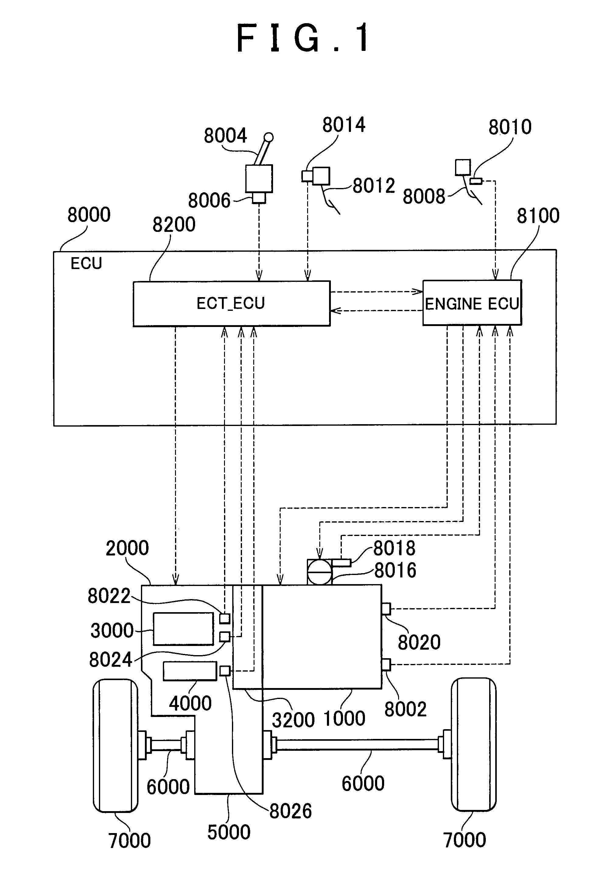
[0028]With reference to FIG. 1, a vehicle equipped with a controller in accordance with an embodiment of the invention will be described. This vehicle is an FF (front engine, front drive) vehicle. However, the vehicle may have a configuration other than the FF vehicle.

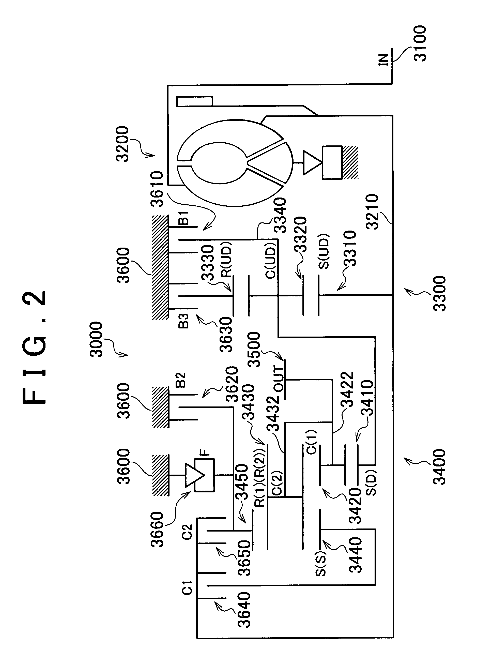
[0029]The vehicle includes an engine 1000, an automatic transmission 2000, a planetary gear unit 3000 that constitutes a portion of the automatic transmission 2000, a hydraulic circuit 4000 that constitutes a portion of the automatic transmission 2000, a differential gear 5000, a drive shaft 6000, front wheels 7000, and an ECU (Electronic Control Unit) 8000. The controller in accordance with the embodiment may be impl...


PUM


Abstract

An ECU executes a program sets a driver requested torque based on the accelerator operation amount, and sets a torque-boost amount so that the torque-boost amount increases as the driver requested torque increases, until the driver requested torque exceeds a predetermined torque T(0). When the driver requested torque exceeds the predetermined torque T(0), the torque-boost amount decreases as the driver requested torque increases. However, the torque obtained by adding the torque-boost amount to the driver requested torque increases as the accelerator operation amount increases.

Description

INCORPORATION BY REFERENCE[0001]The disclosure of Japanese Patent Application No. 2006-209828 filed on Aug. 1, 2006, including the specification, drawings and abstract, is incorporated herein by reference in its entirety.BACKGROUND OF THE INVENTION[0002]1. Field of Invention[0003]The invention relates to a control device and a method of controlling a vehicle. In particular, the invention relates to a technology of performing a torque-boost increase control of a power source during a torque phase of an upshift when causing an automatic transmission to upshift.[0004]2. Description of Related Art[0005]It is known that when an automatic transmission upshifts, the drive force is dropped (is reduced) during the torque phase; the drive force the increases during the transition from the torque phase to the inertia phase, thereby generating a torque shock. To suppress such a shock during a shift, one solution is to boost the torque-boost during the torque phase.[0006]Japanese Patent Applicat...

Claims


Application Information

Patent Timeline
Patent Type & Authority Patents(United States)
IPC IPC(8): B60W10/06B60W10/10F02D29/00F16H59/14F16H59/18F16H59/24F16H61/04F16H61/68F16H61/684F16H61/686F16H63/50
CPCB60W10/06B60W10/115B60W30/19F16H61/0437F16H63/502Y10T477/675F16H61/686F16H59/18
Inventor TOKURA, TAKAAKISUGIMURA, TOSHIOASAMI, TOMOHIROKOBAYASHI, NOBUFUSA
Owner TOYOTA JIDOSHA KK
Why Eureka
Try Eureka