Evaporator
a technology of evaporator and water tank, which is applied in the field of evaporators, can solve the problems of described evaporators and lack of water drainage performance, and achieve the effects of enhancing drainage performance, preventing a drop in the cooling performance of evaporators, and enhancing drainage performan
- Summary
- Abstract
- Description
- Claims
- Application Information
AI Technical Summary
Benefits of technology
Problems solved by technology
Method used
Image
Examples
embodiment 1
[0049]The present embodiment is illustrated in FIGS. 1 to 10.
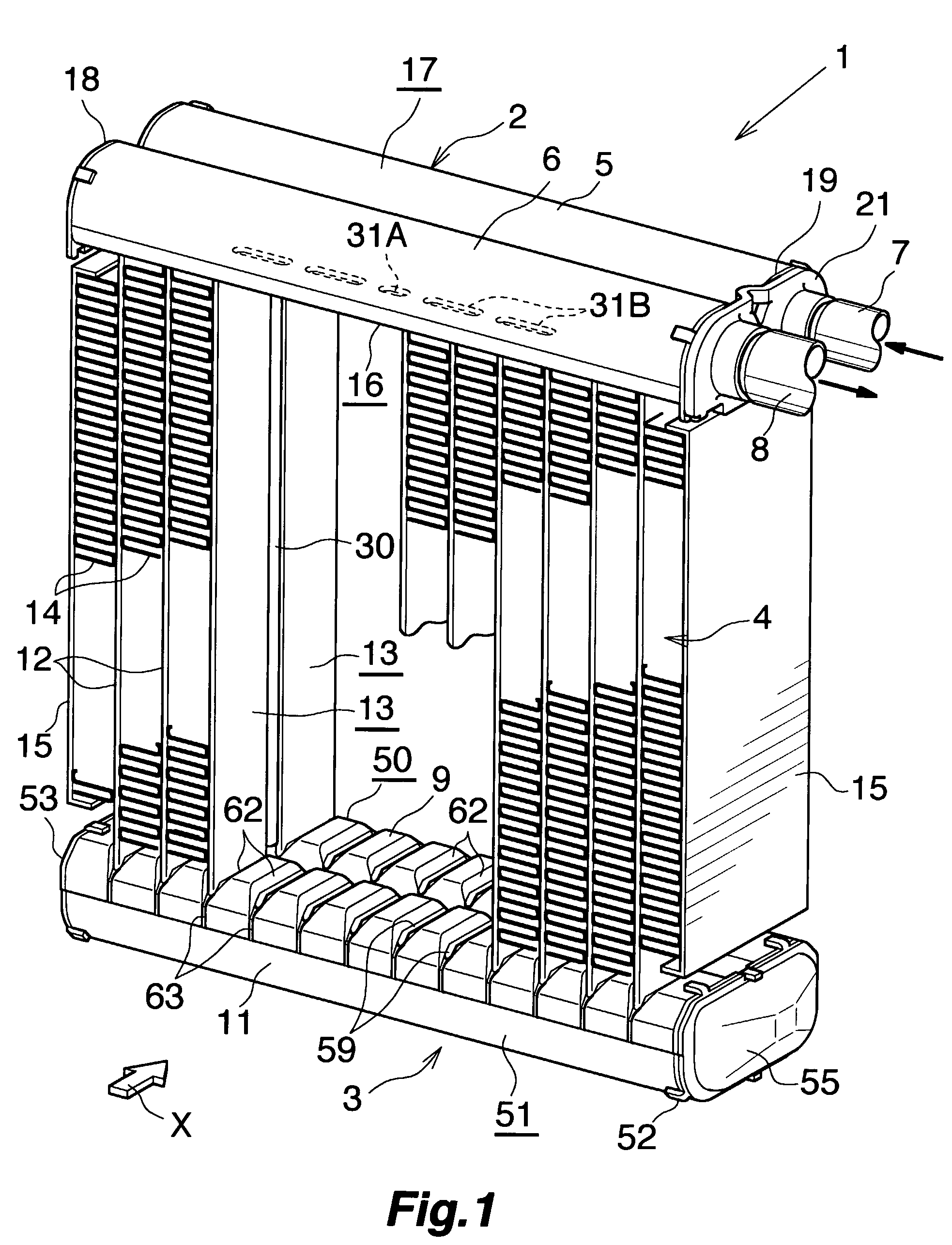
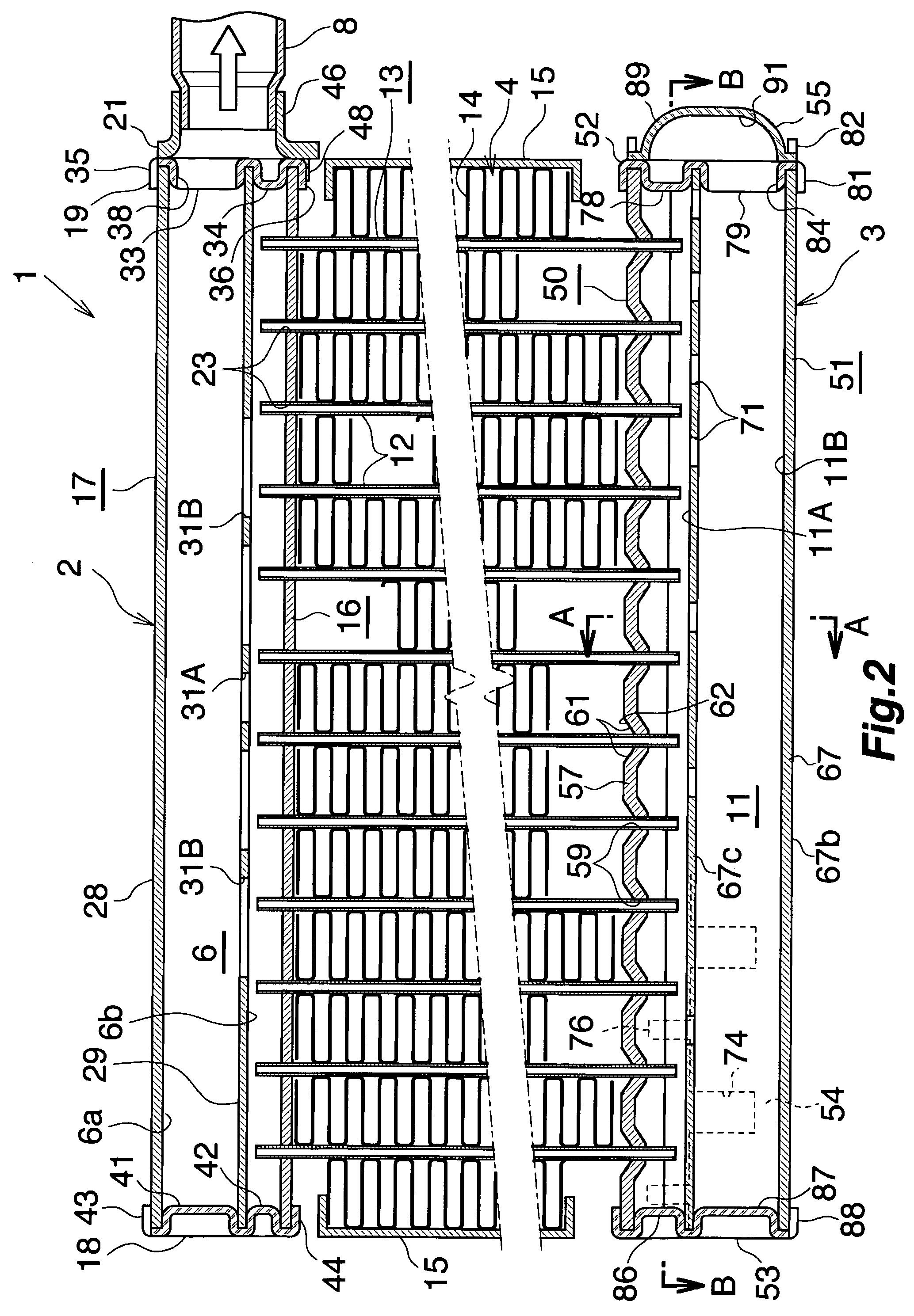
[0050]FIGS. 1 and 2 show the overall configuration of an evaporator, and FIGS. 3 to 9 show the configuration of essential portions of the evaporator. FIG. 10 shows how a refrigerant flows in the evaporator.
[0051]In FIGS. 1 and 2, the evaporator (1), which is used in a car air conditioner using a chlorofluorocarbon-based refrigerant, includes a refrigerant inlet / outlet tank (2) made of aluminum and a refrigerant turn tank (3) made of aluminum, the tanks (2) and (3) being vertically spaced apart from each other, and further includes a heat exchange core section (4) provided between the tanks (2) and (3).
[0052]The refrigerant inlet / outlet tank (2) includes a refrigerant inlet header (5) (first header) located on a side toward the front (downstream side with respect to the air flow direction) and a refrigerant outlet header (6) (second header) located on a side toward the rear (upstream side with respect to the air flow direct...
experiment example 1
[0094]A prepared test assembly was configured such that the heat exchange tubes (12), the drainage acceleration members (30), and the corrugate fins (14) were assembled as in the case of the above-described embodiment, but the refrigerant inlet / outlet tank (2) and the refrigerant turn tank (3) were not attached thereto. The heat exchange tubes (12) and the drainage acceleration members (30) have a thickness h of 1.4 mm as measured in the left-right direction; the gap (70) between the heat exchange tubes (12) and the corresponding drainage acceleration members (30) has a width w of 0.25 mm as measured in the front-rear direction; the drainage acceleration members (30) have a width of 3.5 mm as measured in the front-rear direction; the corrugate fins (14) have a fin height (H) of 8 mm; and the fin pitch (P) is 1.5 mm. Opposite end openings of the heat exchange tubes (12) and those of the drainage acceleration members (30) were closed. The test assembly was immersed in water contained ...
embodiment 2
[0097]This embodiment is shown in FIG. 12.
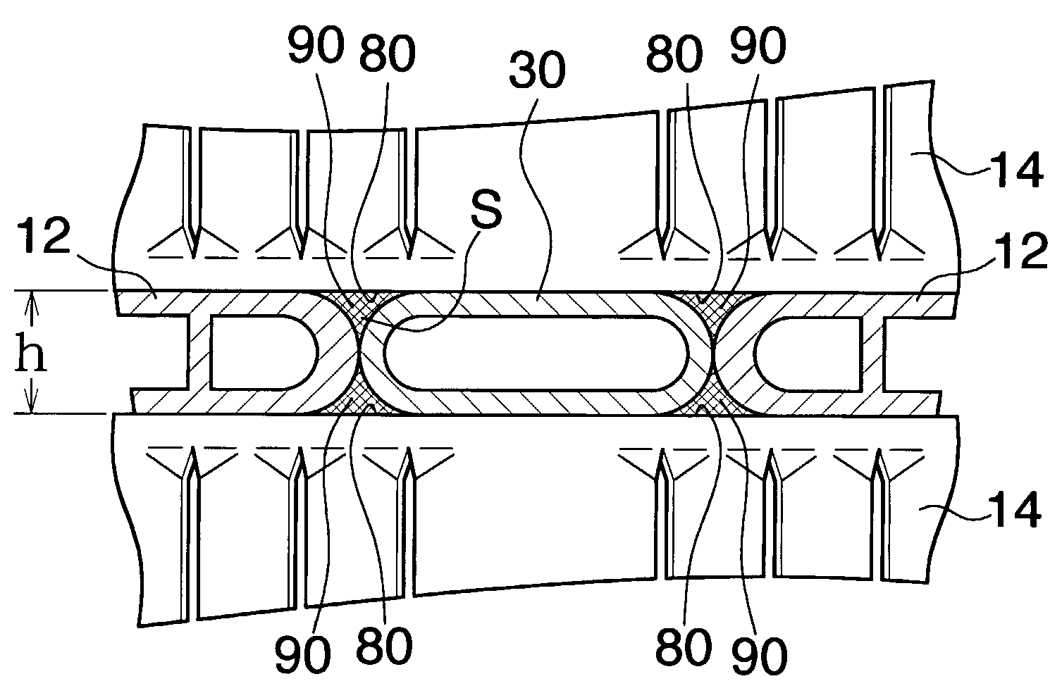
[0098]In Embodiment 2, the outer surface of the inner end wall with respect to the front-rear direction of the front heat exchange tube (12) and the front end surface of the drainage acceleration member (30) are in contact with each other, and the outer surface of the inner end wall with respect to the front-rear direction of the rear heat exchange tube (12) and the rear end surface of the drainage acceleration member (30) are in contact with each other. Recesses (90) are formed between the front heat exchange tube (12) and the drainage acceleration member (30) and between the rear heat exchange tube (12) and the drainage acceleration member (30) in such a manner as to be depressed inward with respect to the left-right direction from extension surfaces of the left and right side surfaces of the heat exchange tubes (12) and to extend vertically. The recesses (90) serve as drain channels (80). Preferably, the relation 0.05≦S / h≦1.5 is satisfied...
PUM
 Abstract
Description
Claims
Application Information
 - R&D
- Intellectual Property
- Life Sciences
- Materials
- Tech Scout
- Unparalleled Data Quality
- Higher Quality Content
- 60% Fewer Hallucinations
Browse by: Latest US Patents, China's latest patents, Technical Efficacy Thesaurus, Application Domain, Technology Topic, Popular Technical Reports.
© 2025 PatSnap. All rights reserved.Legal|Privacy policy|Modern Slavery Act Transparency Statement|Sitemap|About US| Contact US: help@patsnap.com


