
Method for making an electromagnetically excitable core of an electrical machine with a multiphase winding

a technology of electrical machines and electromagnetic excitability, which is applied in the manufacture of stator/rotor bodies, magnetic bodies, manufacturing tools, etc., can solve problems such as unsatisfactory noise, and achieve the effects of reducing bending forces during manufacturing of individual phase windings, increasing groove filling, and simplifying the manufacturing process

Inactive Publication Date: 2010-06-01
SEG AUTOMOTIVE GERMANY GMBH
View PDF14 Cites 14 Cited by
  • Summary
  • Abstract
  • Description
  • Claims
  • Application Information

AI Technical Summary

Benefits of technology

[0007]Because of the arrangement of the phase windings according to the invention the approximately wedge-shaped opening of the prior art core can be at least partially closed. This has the effect that the stator-dependent noise generation caused by the flowing cooling air is significantly reduced.
[0008]Features of the preferred embodiments are described hereinbelow. When one of the phase windings is constructed so that the winding overhang of this phase winding includes only one part of the coil sides provided for the corresponding groove, the winding overhang may be inserted comparatively simply into the appropriate groove on bending the core with the winding. The manufacturing process is thus simply formed, the danger of manufacturing interruptions and the danger of defects in the winding due to the manufacturing method are clearly reduced.
[0009]According to another embodiment of the invention it is provided that all phase windings are wound equally. One of the phase windings with first coil sides is inserted in one groove, which is spaced electrically from the first groove of the core about 240 degrees. A complete winding overhang thus results from a phase winding. Because of that in contrast to the previous embodiments of the invention all phase windings are equal, the manufacturing process for the individual phase windings is reduced to only one type of manufacturing process, the manufacturing process is clearly simplified and costs are considerably reduced.
[0012]According to another preferred embodiment the phase windings are wound from a multiple wire. This means that a so-called simple wire is not used, which is wound around a winding mold, but several wires are used, whose diameter is reduced in comparison to the diameter of an individual wire. Because of that the bending forces during manufacture of the individual phase windings are reduced and thus the forces applied to the wires are not too large. The smaller the loads on the multiple wire, the smaller the danger of manufacturing errors during the forming of the individual phase windings. According to another preferred embodiment it is provided that all phase windings are pressed into a mold prior to insertion in the core and thus the coil sides provided for each groove are shaped jointly in a predetermined groove shape. This means that not every individual phase winding is laid by itself in the core, but all three phase windings are laid together in the mold and after shaping are inserted together in the electromagnetically excitable core, i.e. in its grooves. This again simplifies the manufacturing process, since the three windings need not be inserted one after the other in the core, but this process can be completed in a single insertion step.
[0013]According to another preferred embodiment of the invention the shaping groove of the mold includes a groove slot. This means that the total cross-section of the coil sides in the mold is not only pressed in the shaping groove between yoke back and the undersides of the teeth ends, but that the wires to be pressed are shaped so that they can at least partially fill even the groove slot in the electromagnetically excitable core. This has the result that the stator made in this process can have increased groove filling, since now also the wires can be laid in the groove slot.

Problems solved by technology

These wedge-like openings or recesses on the periphery of the stator produce a passage for cooling air, which can lead to undesirable noise under some circumstances.

Method used


Image

  • Method for making an electromagnetically excitable core of an electrical machine with a multiphase winding
  • Method for making an electromagnetically excitable core of an electrical machine with a multiphase winding
  • Method for making an electromagnetically excitable core of an electrical machine with a multiphase winding

Examples


Embodiment Construction

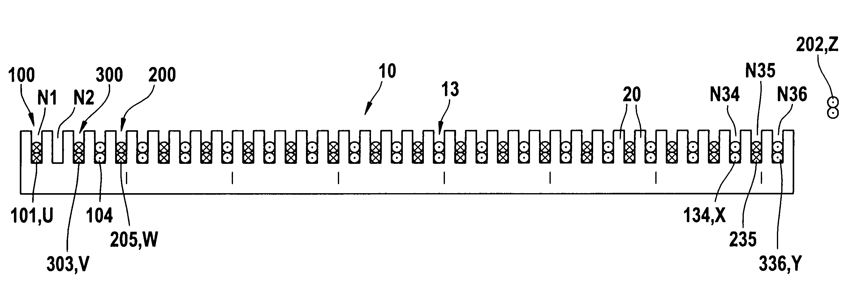
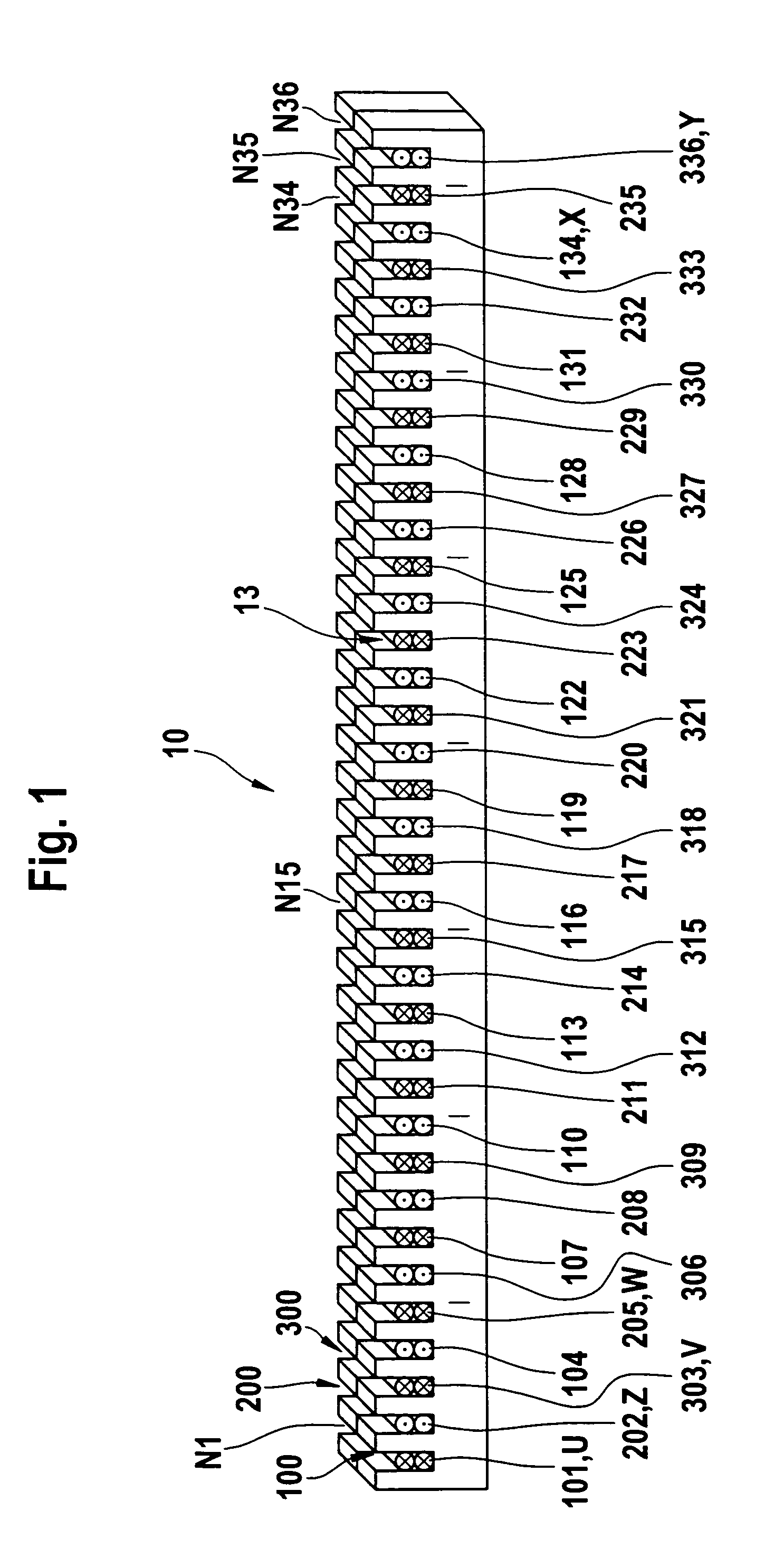
[0029]FIG. 1 is a schematic perspective view of an electromagnetically excitable core 10, which is provided for an electrical machine. An alternator for a motor vehicle is a preferred embodiment of the electrical machine. A multiphase winding 13 is used in this core 10. This multiphase winding 13 is embodied as a so-called three-phase winding as shown in FIG. 1.

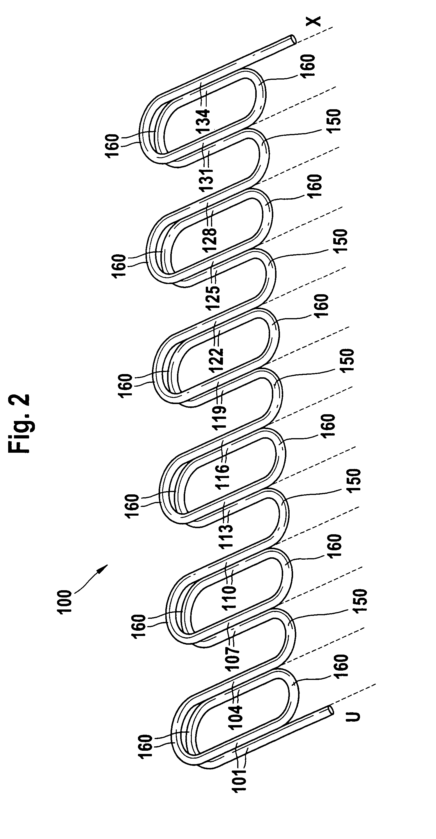
[0030]The first phase winding 100 includes both the coil sides 101 to 134 shown in FIG. 1, and also the coil side connectors 150 not shown in FIG. 1 and the coil side connectors 160, see FIG. 2. The beginning and ending of the first phase winding 100 are indicated with the alphabetic reference characters U and X, as usual.

[0031]Furthermore the second phase winding 200 is shown in FIG. 1 similarly with the coil sides 202 to 235 and the third phase winding 300 is shown with the coil sides 303 to 336. The coil sides 101 to 336 are inserted in the grooves N1 to N35 of the core 10. The designation of these grooves relates to their...


PUM

PropertyMeasurementUnit
shapeaaaaaaaaaa
diameteraaaaaaaaaa
bending forcesaaaaaaaaaa

Abstract

The method of making an electromagnetically excitable core of an electrical machine with a multiphase winding (13) includes preparing a core (10) having a substantially parallelepiped shape, which is provided with a plurality of parallel grooves (N1 to N36; N1 to N48) in one side in a first step. In at least one subsequent step at least three phase windings (100, 200, 300) are laid in these grooves in such a manner that only one winding overhang is outside of the core.

Description

CROSS-REFERENCE[0001]The invention described and claimed hereinbelow is also described in 103 29 572.0, filed Jun. 30, 2003. This German Patent Application, whose subject matter is incorporated here by reference, provides the basis for a claim of priority of invention under 35 U.S.C. 119 (a)-(d).BACKGROUND OF THE INVENTION[0002]The present invention relates to a method of making an electro-magnetically excitable core of an electrical machine with a multiphase winding, especially a stator of an alternator, and, more particularly, to a method of making an electromagnetically excitable core of an electrical machine with a multiphase winding, in which a core having a substantially parallelepiped shape is provided with a plurality of grooves in one side spaced from each other along the core, and at least three phase windings are laid in the grooves of the core.[0003]A method of making an electromagnetically excitable core with a multiphase winding is disclosed in International Patent Pub...

Claims


Application Information

Patent Timeline
Patent Type & Authority Patents(United States)
IPC IPC(8): H02K15/00H02K1/00H02K3/28H02K15/02H02K15/04H02K15/06
CPCH02K3/28H02K15/024H02K15/06H02K15/066Y10T29/49073Y10T29/5141Y10T29/4902Y10T29/49071Y10T29/49009
Inventor STROEBEL, WOLFGANGSCHEIFFELE, HELMUT
Owner SEG AUTOMOTIVE GERMANY GMBH
Learn More