
Drive control unit, drive control method and image forming apparatus

a technology of drive control and image forming apparatus, which is applied in the direction of electrographic process apparatus, printing, instruments, etc., can solve the problems of difficult to completely eliminate the fluctuation in difficult to perfectly match the rotational speed of the plurality of photoconductive drums, and generate similar registration errors to the drive control system, etc., to reduce the registration error of color images, and reduce the color image registration error

Inactive Publication Date: 2010-05-25
RICOH KK
View PDF12 Cites 2 Cited by
  • Summary
  • Abstract
  • Description
  • Claims
  • Application Information

AI Technical Summary

Benefits of technology

This approach effectively reduces registration errors in color images by synchronizing the rotational speeds of photoconductive drums, ensuring accurate overlapping of toner images, even when fluctuations occur, thereby improving image formation quality.

Problems solved by technology

However, since the plurality of photoconductive drums are controlled independently, it is difficult to perfectly match the rotational speeds of the plurality of photoconductive drums.
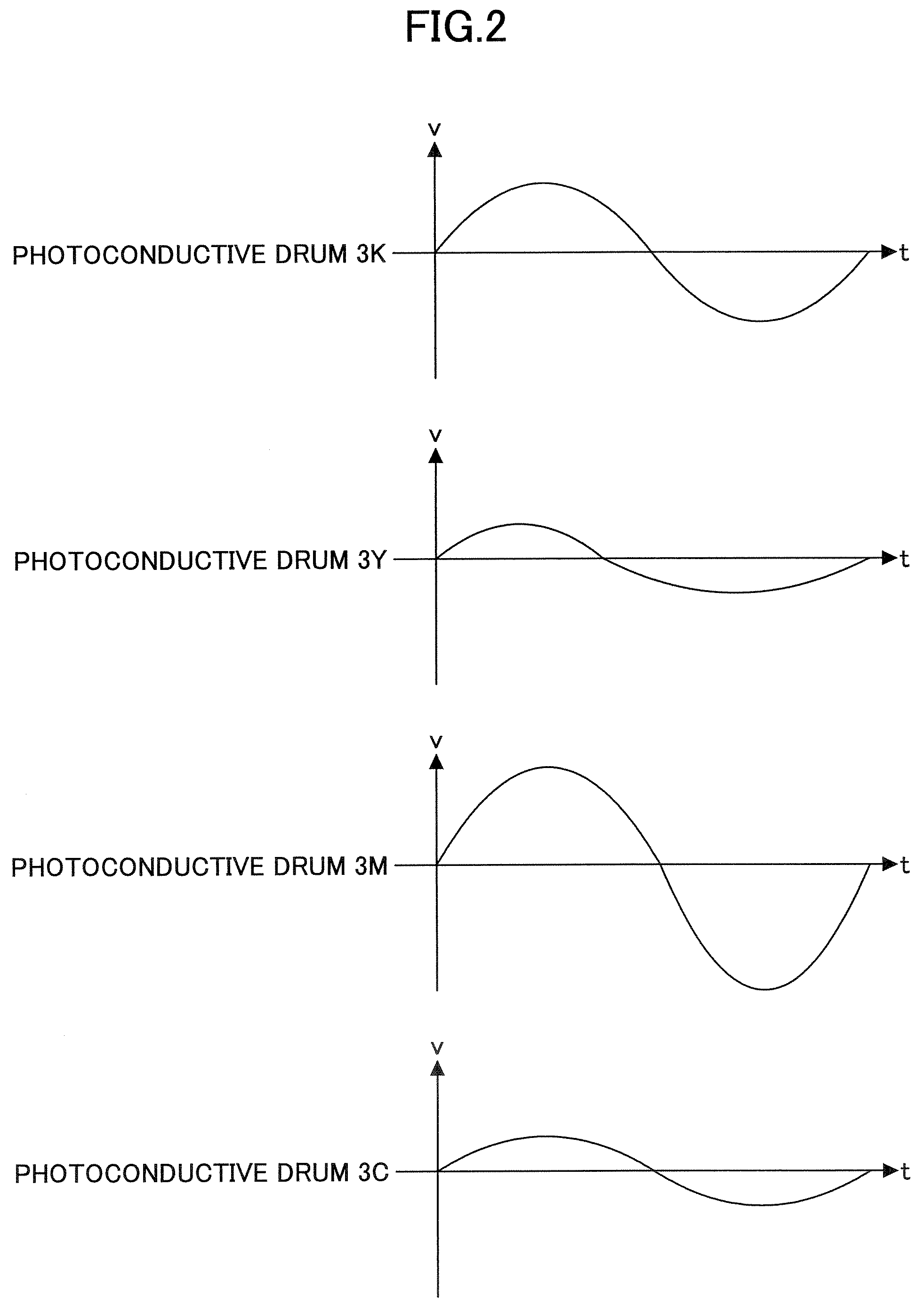
In other words, in the case of the tandem method, even if a target rotational speed is set with respect to each of the plurality of photoconductive drums, each photoconductive drum undergoes a fluctuation in its rotational speed that is peculiar to each photoconductive drum, due to eccentricity of a drum shaft and mounting error of a driving part and the photoconductive drum itself.
As a result, the registration error in which the overlapping toner images of the different colors do not match on the transfer member is caused by the fluctuations in the rotational speeds of the plurality of photoconductive drums.
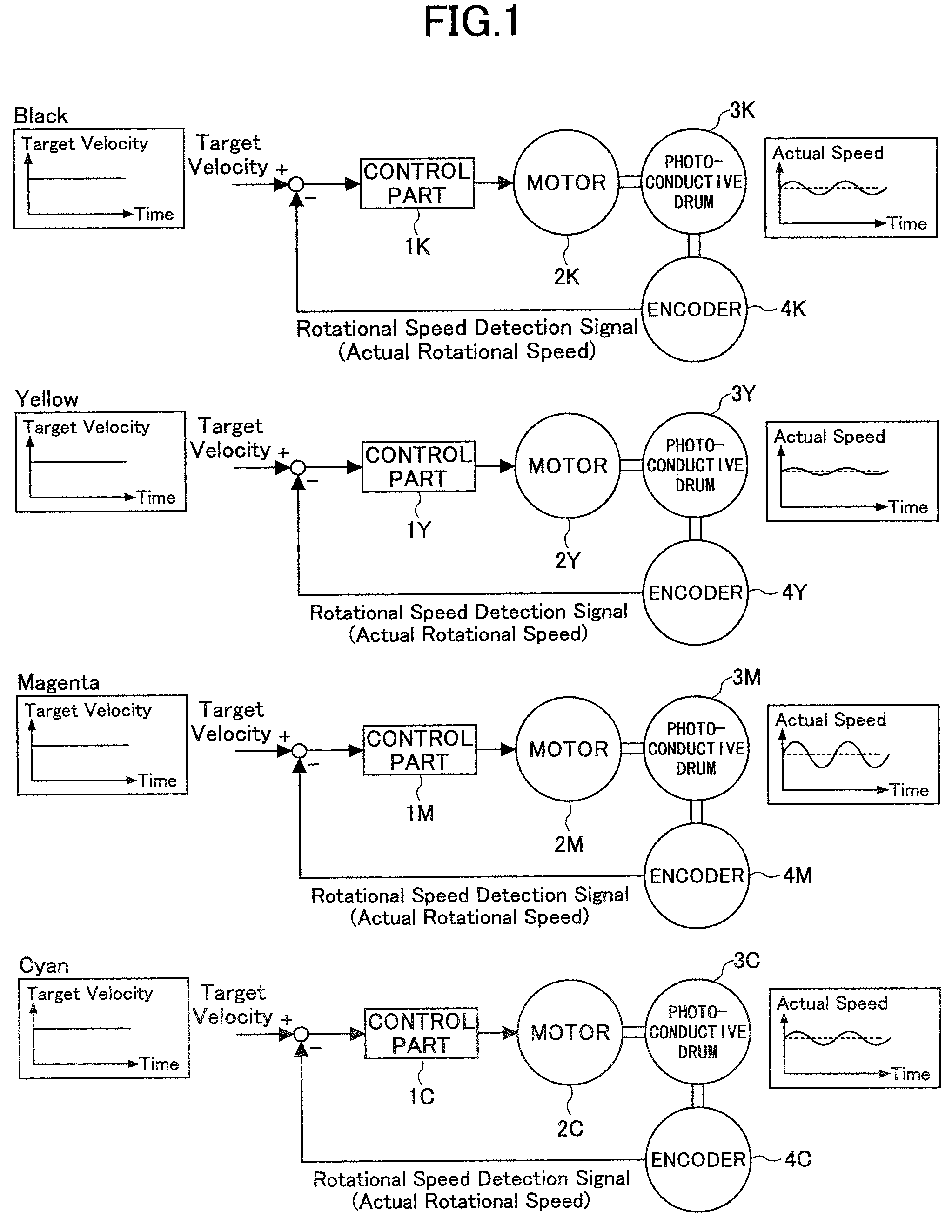
However, even though the drive control unit having the structure shown in FIG. 1 controls the rotational speed of the motor 2K depending on the difference between the constant target rotational speed and the actual rotational speed that are fed back from the encoder 4K, the photoconductive drum 3K undergoes a fluctuation in its rotational speed that is peculiar to the photoconductive drum 3K, due to the eccentricity of the drum shaft and the mounting error of the driving part and the photoconductive drum 3K itself.
As a result, the registration error in which the overlapping toner images of the different colors do not match on the transfer member is caused by the fluctuations in the rotational speed of the photoconductive drum 3K.
In addition, in the drive control systems for yellow, magenta and cyan, the registration error is generated similarly to the drive control system for black.
For this reason, even if the rotational speeds of the photoconductive drums are controlled to approximate the target rotational speed, it is difficult to completely eliminate the fluctuation in the rotational speeds of the photoconductive drums and to perfectly match the rotational speeds of each of the photoconductive drums.

Method used


Image

  • Drive control unit, drive control method and image forming apparatus
  • Drive control unit, drive control method and image forming apparatus
  • Drive control unit, drive control method and image forming apparatus

Examples


Embodiment Construction

[0032]A description will be given of embodiments of a drive control unit, a drive control method and an image forming apparatus according to the present invention, by referring to FIG. 3 and the subsequent figures.

[0033]FIG. 3 is a diagram showing a general structure of the image forming apparatus. The image forming apparatus shown in FIG. 3 has image forming parts 401Y, 401M, 401C and 401K for forming yellow, magenta, cyan and black images, respectively. The image forming parts 401Y, 401M, 401C and 401K are arranged in line along a transport belt 411 which transports a transfer member 410 which may be a sheet of paper or a suitable recording medium. The transport belt 411 is supported by a driving roller 412 which drives and revolves the transport belt 411, and a following roller 412 which follows the revolving the transport belt 411. The transport belt 411 is driven to revolve in a direction indicated by an arrow in FIG. 3 by the rotation of the driving roller 412.

[0034]A paper su...


PUM


Abstract

A drive control unit for controlling speeds of driving parts based on a target speed, includes a detecting part to detect speed fluctuations of each of the driving parts when the speeds of the driving parts are controlled based on a common target speed, a storage part to store speed fluctuation profiles of each of the driving parts created based on the detected speed fluctuations, an extracting part to extract a speed fluctuation profile having a largest amplitude of the speed fluctuation profiles stores in the storage part, a calculating part to calculate difference profiles of the driving parts, corresponding to differences between the extracted speed fluctuation profile and the speed fluctuation profiles of each of the driving parts, a setting part to set the difference profiles of the driving parts as new target speeds of the driving parts, and a control part to control the speeds of the driving parts based on the new target speeds.

Description

BACKGROUND OF THE INVENTION[0001]1. Field of the Invention[0002]The present invention generally relates to drive control units, drive control methods and image forming apparatuses, and more particularly to a drive control unit and a drive control method for controlling speeds of a plurality of driving parts, and an image forming apparatus which employs such a drive control unit or drive control method.[0003]2. Description of the Related Art[0004]Conventionally, as methods of forming color images, there are the intermediate transfer method and the tandem method. The intermediate transfer method forms a toner image on one photoconductive drum, one color at a time, and obtains the full color image by successively transferring the toner images of different colors on a transfer member. The tandem method arranged a plurality of photoconductive drums in parallel, forms the toner image of one color at each photoconductive drum, and obtains the full color image by successively transferring t...

Claims


Application Information

Patent Timeline
Patent Type & Authority Patents(United States)
IPC IPC(8): G03G15/01
CPCG03G15/5008G03G2215/00075
Inventor KIRYU, KOJI
Owner RICOH KK
Learn More