
Roller chain for a linear guideway

a technology of roller chain and linear guideway, which is applied in the direction of conveyor parts, mechanical equipment, transportation and packaging, etc., can solve the problems of insufficient space for lubricant in the roller chain itself, labourious and time-consuming roller chain, and inability to prevent indirect impact, so as to reduce impact-caused noise, prevent indirect impact, and effectively absorb impact force

Active Publication Date: 2010-05-25
HIWIN TECH
View PDF14 Cites 12 Cited by
  • Summary
  • Abstract
  • Description
  • Claims
  • Application Information

AI Technical Summary

Benefits of technology

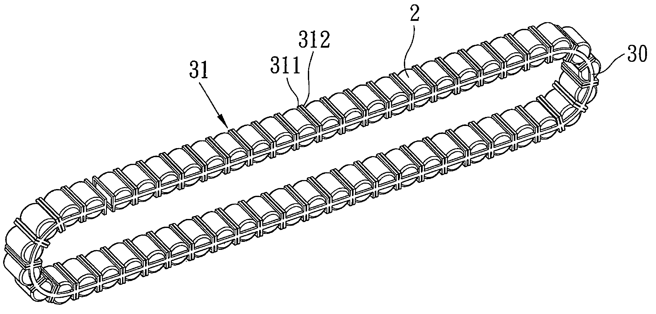
The present invention provides a roller chain for a linear guideway that prevents impact between neighboring rollers caused by the spacer between them, effectively absorbing the impact force while reducing the impact-caused noise. The roller chain comprises a plurality of spacers and two links, each spacer having two retaining portions that hold the rollers, and the links connect the spacers together. The roller chain is made of flexible material and has a flat inner surface with a predetermined thickness, allowing the retaining portions to be in line-to-line contact with the rollers. The spacers are flexible and made by injection molding, which facilitates mass production.

Problems solved by technology

Therefore, making such a roller chain is laboursome and time-consuming.
The disadvantages of this kind of roller chain are explained below:
1. Indirect impact will be caused between neighboring rollers 70 via the connecting portions 5a.
2. The contacting area of the spacers 6 with respect to the rollers 70 is large, thus increasing the rolling resistance.
3. The roller chain itself doesn't have enough space to reserve lubricant.
4. It is very difficult to manufacture such a roller chain structure.
2. both ends 20 of the rollers are drilled with holes 16, and this will not only increase the production cost but will reduce the strength of the rollers 13a.
3. The roller chain itself doesn't have enough space to reserve lubricant.

Method used


Image

  • Roller chain for a linear guideway
  • Roller chain for a linear guideway
  • Roller chain for a linear guideway

Examples


Embodiment Construction

[0048]The foregoing, and additional objects, features and advantages of the present invention will become apparent from the following detailed description of preferred embodiments thereof, taken in conjunction with the accompanying drawings.

[0049]Referring to FIGS. 4, 5a, and 5b, a linear guideway 1 in accordance with the present invention comprises a rail 1a and a slide block 1b. The rail 1a is an elongated structure defined with rolling grooves 12 for the rollers. The slide block 1b is a reverse U-shaped structure defined with grooves for cooperating with the rolling groove 12 of the rail 1a, defining a rolling path for allowing the rollers 2 to circulate therein. To enable the rollers 2 to circulate endlessly, the slide block 1b must be provided at either end thereof with an end cap 1c, and a re-circulation path 11 is formed in the end cap 1c.

[0050]FIG. 6 is an illustrative view in accordance with the present invention of showing the rollers' circulation route. FIG. 7 is an asse...


PUM


Abstract

A roller chain for a linear guideway comprises: a plurality of spacers each having two retaining portions and two links, each retaining portion is a hollow structure for holding the rollers. The retaining portions are formed at both sides of the rollers, one side of each of the retaining portions is opposite to the rollers, and another side doesn't contact any component, so that each two neighboring rollers are separated from each other completely. Each link is an elongated structure located at both ends of the rollers and employed to connect the spacers together. Hence, the impact energy caused when the spacer is impacted by the rollers will be converted into elastic energy, which prevents the indirect impact of two neighboring rollers caused by the spacer therebetween, thus effectively absorbing the impact force while substantially reducing the impact-caused noise.

Description

[0001]This application is a continuation of part of U.S. patent application Ser. No. 11 / 470,248, which claims the benefit of the earlier filing date of Sep. 5, 2006 now abandoned. Claim 1 of the this application is a combination of the claims 1, 2 and 3 of U.S. patent application Ser. No. 11 / 470,248, and claims 2-6 of the this application correspond to the previous 4-8 of U.S. patent application Ser. No. 11 / 470,248.BACKGROUND OF THE INVENTION[0002]1. Field of the Invention[0003]The present invention relates to a roller chain for a linear guideway, and more particularly to prevent the indirect impact between two neighboring rollers caused by the spacer therebetween, thus substantially reducing the impact-caused noise.[0004]2. Description of the Prior Art[0005]The existing linear guideway essentially comprises a rail and a slide block. The rail is an elongated structure defined with rolling grooves for allowing the rollers to circulate therein. The slide block is reverse U-shaped and ...

Claims


Application Information

Patent Timeline
Patent Type & Authority Patents(United States)
IPC IPC(8): B65G17/24
CPCF16C33/506F16C29/065
Inventor CHEN, TSUNG-JEN
Owner HIWIN TECH
Learn More