
Buffer for explosive device

Inactive Publication Date: 2010-05-25
BAKER HUGHES HLDG LLC
View PDF6 Cites 35 Cited by
  • Summary
  • Abstract
  • Description
  • Claims
  • Application Information

AI Technical Summary

Problems solved by technology

The ensuing shock and vibration of the pressure wave PW is sufficiently large damage to damage other downhole tools in the wellbore 1 or proximate to the ballistics device.

Method used


Image

  • Buffer for explosive device
  • Buffer for explosive device
  • Buffer for explosive device

Examples


Embodiment Construction

[0017]The present invention will now be described more fully hereinafter with reference to the accompanying drawings in which embodiments of the invention are shown. This invention may, however, be embodied in many different forms and should not be construed as limited to the illustrated embodiments set forth herein; rather, these embodiments are provided so that this disclosure will be thorough and complete, and will fully convey the scope of the invention to those skilled in the art. Like numbers refer to like elements throughout. For the convenience in referring to the accompanying figures, directional terms are used for reference and illustration only. For example, the directional terms such as “upper”, “lower”, “above”, “below”, and the like are being used to illustrate a relational location.

[0018]It is to be understood that the invention is not limited to the exact details of construction, operation, exact materials, or embodiments shown and described, as modifications and equ...


PUM


Abstract

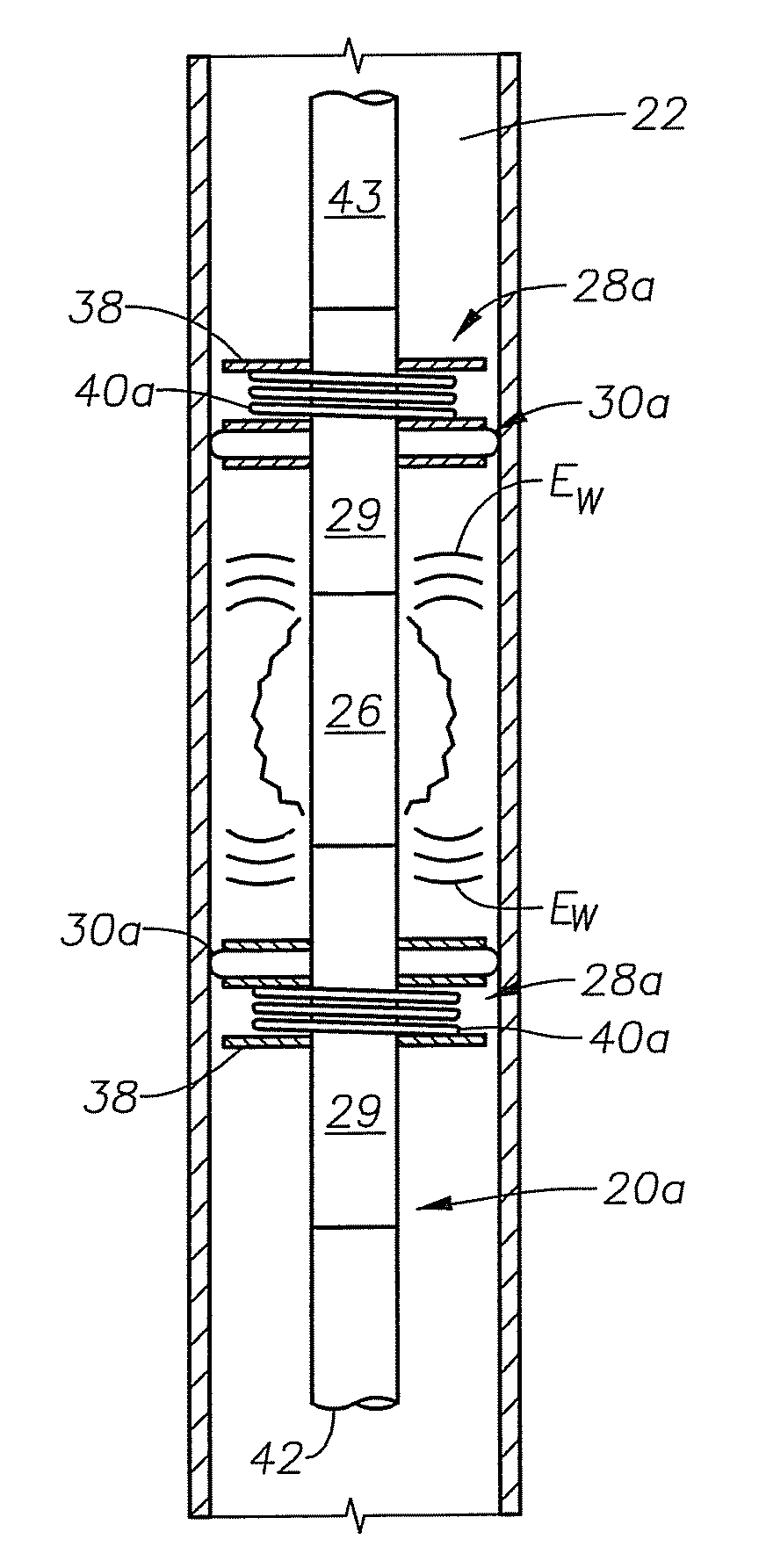
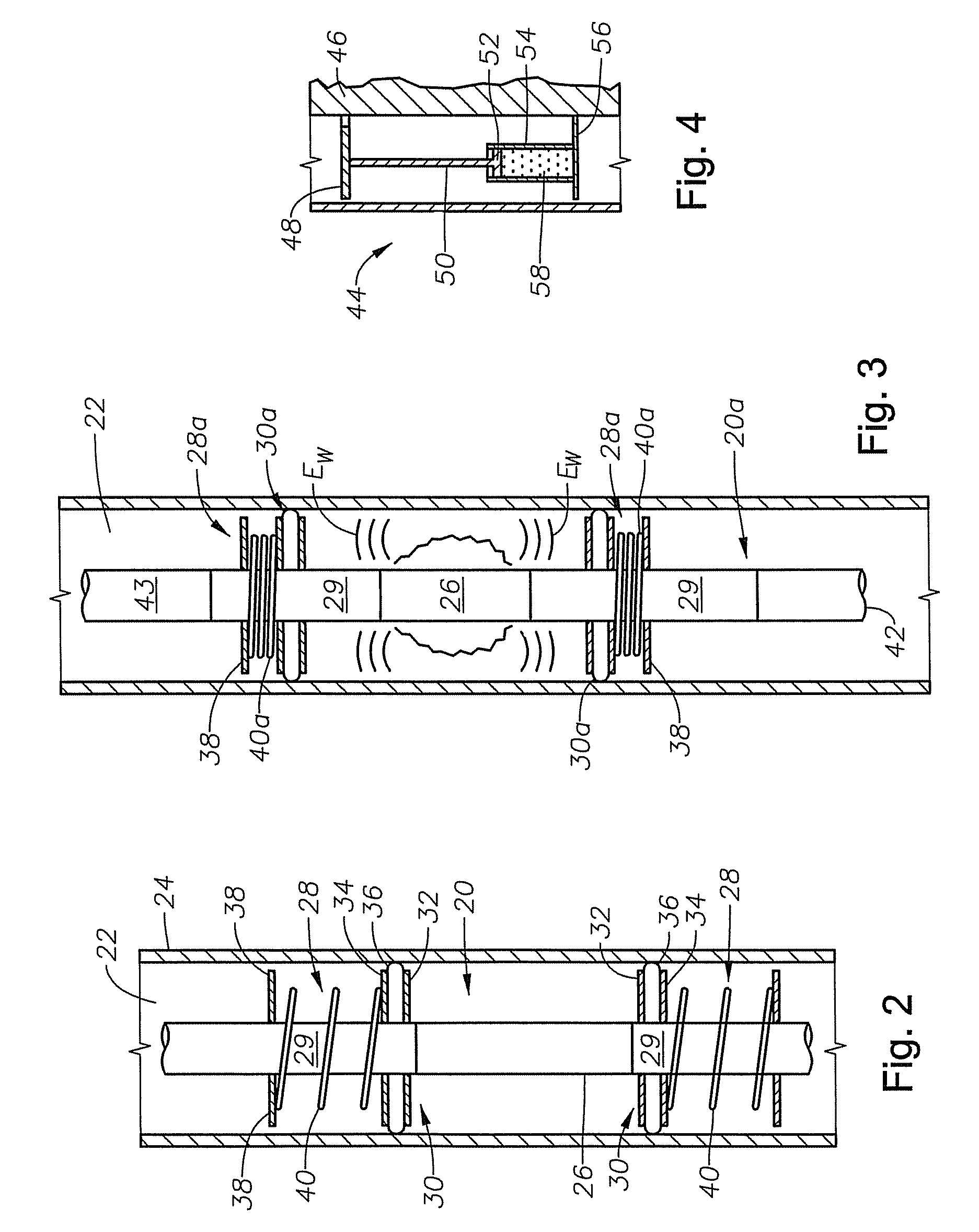
A buffering device for use in conjunction with a downhole tool string, wherein the tool string includes a ballistics device. The buffering device includes a mandrel attached within a tool string and proximate to the ballistics device. An anchor is disposed on the mandrel and a disk plate is coaxially placed on the mandrel that is slideable thereon. The disk plate is proximate to the ballistic device. A resilient member, such as a spring, is coaxially placed on the mandrel between the disk plate and the anchor. The pressure wave produced by activation of the ballistic device pushes the disk plate toward the anchor and compresses the spring there between. Since the disk plate extends outward into sealing contact with casing lining the wellbore, compression of the spring dissipates energy waves produced by activation of the ballistic device.

Description

BACKGROUND[0001]1. Field of Invention[0002]The invention relates generally to the field of oil and gas production. More specifically, the present invention relates to a system for buffering explosions produced during wellbore operations.[0003]2. Description of Prior Art[0004]Various operations are conducted in a hydrocarbon producing wellbore that generate an explosion and / or percussive pressure wave in the wellbore. Such operations include wellbore perforating, a back-off shot, roll shot, dry pipe shot, and cutting devices. Downhole cutting devices typically sever a tubular member where the portion of the member above the cut is removed. Perforating systems are used for the purpose, among others, of making hydraulic communication passages, called perforations, in wellbores drilled through earth formations so that predetermined zones of the earth formations can be hydraulically connected to the wellbore. Perforations are needed because wellbores are typically completed by coaxially ...

Claims


Application Information

Patent Timeline
Patent Type & Authority Patents(United States)
IPC IPC(8): E21B43/11E21B29/02E21B43/116F42D5/00
CPCE21B43/1195F16F7/00F16F2238/026
Inventor HILL, FREEMAN L.EVANS, RANDY L.
Owner BAKER HUGHES HLDG LLC
Learn More