
Optically anisotropic body and liquid crystal display

a liquid crystal display and anisotropic body technology, applied in the field liquid crystal display, can solve the problems of low yield of optical anisotropic body, unsatisfactory efforts, and degree of screen false color, so as to prevent a drop in contrast and false colors, increase viewing angle, and widen the allowable range

Active Publication Date: 2010-05-18
ZEON CORP
View PDF6 Cites 0 Cited by
  • Summary
  • Abstract
  • Description
  • Claims
  • Application Information

AI Technical Summary

Benefits of technology

The present invention relates to a liquid crystal display with a wide viewing angle and excellent productivity. The technical effect of the invention is achieved by using an optically anisotropic body with specific wavelength dispersion characteristics in the frontal direction retardation value, which allows for a wide viewing angle without a drop in display screen contrast or the occurrence of false colors. The invention also provides a simple method for producing the optically anisotropic body with a high yield production, which in turn improves liquid crystal display productivity.

Problems solved by technology

There remains a great degree of screen false color, however, so these efforts are still unsatisfactory.
This is not a problem if an optically anisotropic body with a phase difference value that fits within this narrow allowable range can be produced in large quantities, but the current production method for the long and wide optically anisotropic bodies used in large displays cannot easily place the phase difference value completely within the allowable range and the optically anisotropic body yield is low, which is an obstacle to improving liquid crystal display productivity.

Method used


Image

  • Optically anisotropic body and liquid crystal display
  • Optically anisotropic body and liquid crystal display
  • Optically anisotropic body and liquid crystal display

Examples


fabrication example 1

[0115]50 mol % of monomer A (Chemical 2) and 50 mol % of monomer B (Chemical 3) having the structures shown below were dissolved in a sodium hydroxide aqueous solution and a small amount of hydrosulfite was added. Next, to this was added methylene chloride and then phosgene was blown in at 20° C. for 60 minutes. Then p-tert-butylphenol was added and emulsified. Triethylamine was added and then this was stirred at 30° C. for 3 hours to complete the reaction. After the reaction was completed, the organic phase was isolated and the methylene chloride was distilled out to obtain a polycarbonate copolymer.

[0116]

example 1

Optically Anisotropic Body A1

[0117]An undrawn layered body comprising a layer [1] comprising 6 parts by weight of 2,2-methylenebis(4-(1,1,3,3-tetramethylbutyl)-6-(2H-benzotriazole-2-yl) phenol) [ADEKASTAB LA-31 made by ASAHI DENKA Co., Ltd] as an ultraviolet light absorption agent exhibiting dichroism, and 100 parts by weight of norbornene resin [ZEONOR 1420R made by Zeon Corporation, glass transition temperature of 136° C.], a layer [2] comprising a copolymer of styrene and maleic anhydride [glass transition temperature of 130° C.], and a layer [3] comprising a denatured copolymer of ethylene and vinyl acetate [Vicat softening point 80° C.] and having the structure of layer [1] (100 μm)-layer [3] (7 μm)-layer [2] (50 μm)-layer [3] (7 μm)-layer [1] (100 μm) was obtained using co-extrusion molding.

[0118]The undrawn layered body was uniaxial drawn in the machine direction at a temperature of 140° C. and a drawing ratio of 1.5 with a drawing machine using the float system between rolls...

fabrication example 2

Fabrication of the Light Polarizer

[0132]A 75 μm polyvinyl alcohol film is allowed to soak for 2 minutes in an aqueous solution containing 0.01 parts by weight of iodine and 2 parts by weight of potassium iodide per 100 parts by weight of water, respectively, at 30° C. while being drawn at a drawing ratio of 3. Next, the film is allowed to soak in an aqueous solution containing 5 parts by weight of boric acid and 3 parts by weight of potassium iodide, respectively, in 100 parts by weight of water at 60° C. for 5 minutes. Then the film is washed with pure water for 10 seconds and allowed to dry at 50° C. for 6 minutes to obtain the light polarizer.


PUM

PropertyMeasurementUnit
wavelength rangeaaaaaaaaaa
wavelengthaaaaaaaaaa

Abstract

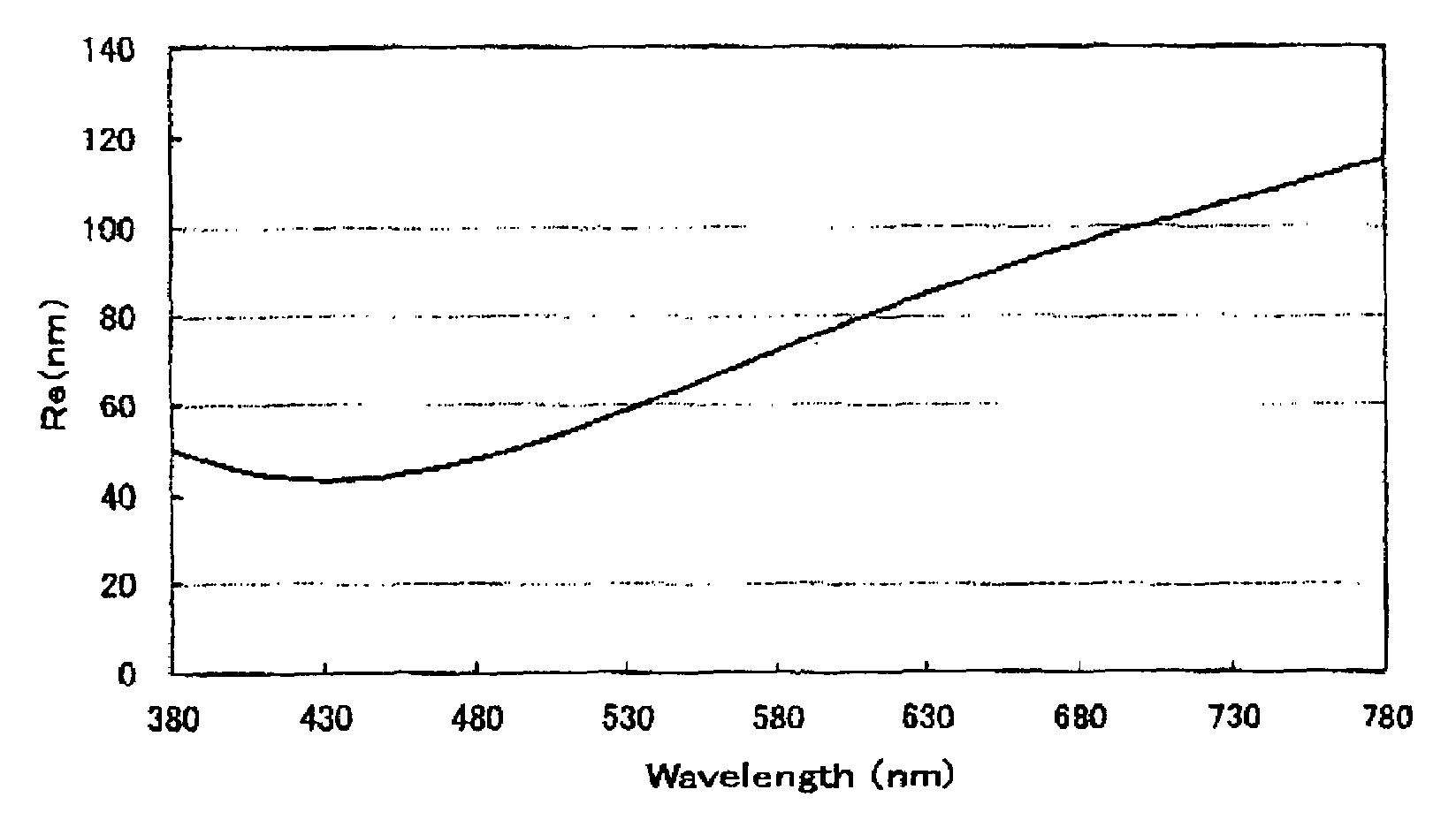
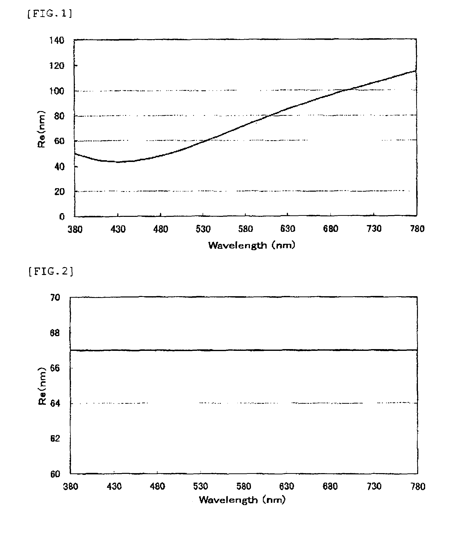
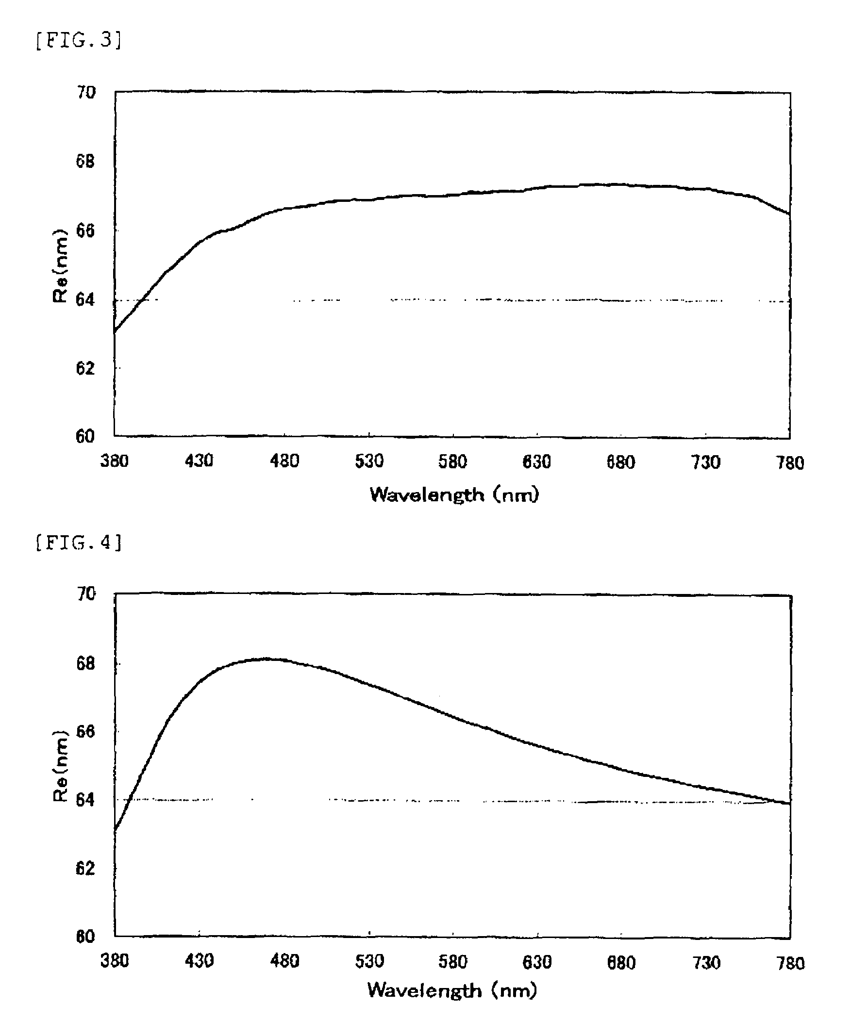
The present invention provides a liquid crystal display that prevents false colors and has a wide viewing angle, display screen contrast that does not decline, and excellent productivity. The liquid crystal display, comprising a liquid crystal cell, a sheet-shaped optically anisotropic body positioned on only one side of the liquid crystal cell, and a pair of light polarizers located on both sides of the liquid crystal cell, wherein the optically anisotropic body satisfies the relationship of nx>ny>nz at wavelength of 550 nm, where nx is in-plane refraction index of lag axis direction, ny is refraction index of the direction perpendicular to the lag axis in the plane, and nz is refraction index of the thickness direction; and has a local minimal value in wavelength range of 380 to 490 nm and monotonous increase in both the short wavelength and long wavelength directions from the wavelength that shows the local minimal value, in wavelength characteristics of frontal direction retardation for light in wavelength range of 380 to 780 nm.

Description

TECHNICAL FIELD[0001]The present invention relates to an optically anisotropic body and liquid crystal display, and more specifically to a vertical alignment mode liquid crystal display with a display screen having a wide viewing angle, the display screen contrast does not drop, false colors are prevented, and productivity is excellent.BACKGROUND ART[0002]Liquid crystal display are classified according to the differences in the liquid crystal drive method (i.e. display mode) in the liquid crystal cell. One of these is the vertical alignment mode (hereinafter referred to as the “VA mode”) liquid crystal display, which is currently the main method utilized for large displays. Further, making liquid crystal displays even large requires a wider viewing angle, so it is preferable for mitigating the screen contrast drop and false colors that occur when a display is viewed from a slant.[0003]For the optically anisotropic body used in the liquid crystal display, patent reference 1 proposes ...

Claims


Application Information

Patent Timeline
Patent Type & Authority Patents(United States)
IPC IPC(8): G02F1/13363
CPCG02B5/3083G02F1/133634G02F1/1393G02F2001/133531G02F2413/14G02F2202/40G02F2203/05G02F2413/12G02F2413/13G02F2001/133742G02F1/133531G02F1/133742G02F1/1335G02F1/13363
Inventor LA, HUNG TRONGOKUDE, SHUHEI
Owner ZEON CORP
Learn More