
Fuel cell system

a fuel cell and system technology, applied in the field of fuel cell systems, can solve the problems of reducing the service life of the fuel cell, acidic water generated in the fuel cell, and degrading the functions of the fuel cell itself, so as to improve the refinement (or purification) efficiency, reduce pressure loss, and increase flow resistance

Inactive Publication Date: 2010-05-18
TOYOTA JIDOSHA KK
View PDF38 Cites 0 Cited by
  • Summary
  • Abstract
  • Description
  • Claims
  • Application Information

AI Technical Summary

Benefits of technology

The invention provides a fuel cell system with an improved exhaust gas system that can remove moisture particles and impurities from the exhaust gas. This system includes an exhaust gas passage with an impurity removal member placed inside it. The impurity removal member can be a separate device or a part of the fuel cell system itself. The system also includes a gas-liquid separator and an accommodating member that can adjust to changes in the volume of the impurity removal member. The technical effects of this invention include improved performance, increased efficiency, and longer lifespan of the fuel cell system.

Problems solved by technology

In particular, if metal ions exist in the components dissolving from, for example, piping parts of the fuel cell or the system, there is the possibility that the functions of the fuel cell itself may be degraded and the service life of the fuel cell may be shortened.
In addition, the water generated in the fuel cell may become acidic.
If this fuel cell system is to be mounted on an automobile or similar, an extra loading space is needed.
However, the filter provided in the fuel cell system described in JP-A-8-298130 is used to remove impurities such as iron molds and salts contained in the cathode gas, and is not intended to securely remove impurities contained in moisture particles mixed in the cathode gas.
Moreover, the ion removal unit provided in the fuel cell system described in JP-A-2002-313404 is used to remove ions contained in the generated water flowing through pipes, and is not intended to remove impurities contained in the moisture particles mixed in the exhaust gas discharged from the fuel cell.
Therefore, the fuel cell coolant circulation apparatus is not designed to have the cartridge-type ion exchanger placed at a position in a gas-liquid separator where the ion exchanger would not disturb efficient separation between liquid and gas.

Method used


Image

  • Fuel cell system
  • Fuel cell system
  • Fuel cell system

Examples


Embodiment Construction

[0065]Preferred embodiments of this invention will be described below in detail with reference to the attached drawings. The embodiments described below are for the purpose of describing this invention, but the invention is not limited only to these embodiments. Accordingly, this invention can be implemented in various ways unless the utilizations depart from the gist of the invention.

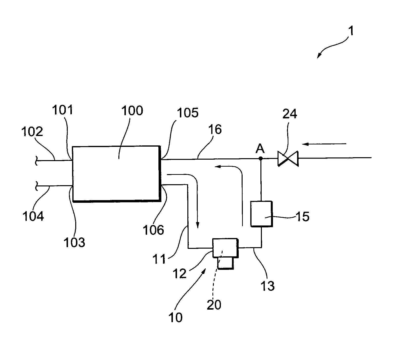
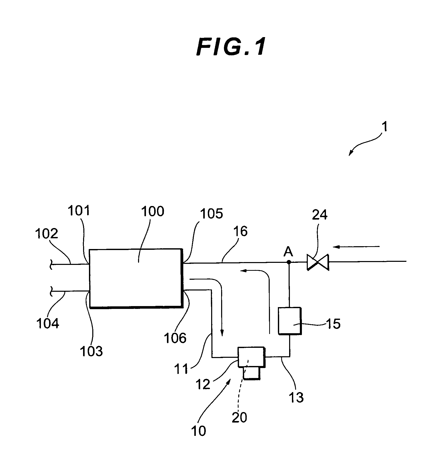
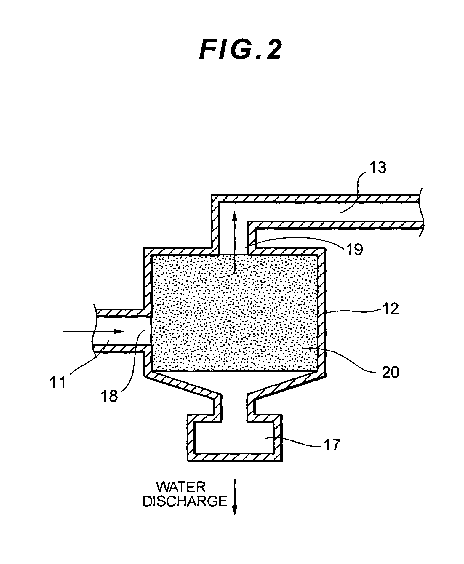
[0066]FIG. 1 is a schematic configuration diagram of a fuel cell system according to an embodiment of the invention. FIG. 2 is an enlarged cross-sectional view schematically showing the configuration of the area around a gas-liquid separator and an ion exchange resin member of the fuel cell system in FIG. 1.

[0067]In this embodiment, a circulation passage provided in a hydrogen circulation system will be described as an example of an exhaust gas passage connected to a fuel cell to allow an exhaust gas from the fuel cell to flow through.

[0068]As shown in FIG. 1, a fuel cell 100 of a fuel cell system 1 ac...


PUM

PropertyMeasurementUnit
flow resistanceaaaaaaaaaa
ion exchangeaaaaaaaaaa
volumeaaaaaaaaaa

Abstract

A fuel cell system (1) capable of securely removing moisture in particulate form floating in an exhaust gas passage along with impurities mixed in the moisture, enhancing the performance of a fuel cell, and extending the service life of the fuel cell. The fuel cell system (1) includes a gas circulation system for recirculating and resupplying an exhaust gas to a fuel cell (100). This gas circulation system is equipped with an ion exchange resin member (20) that adsorbs impurity components contained in the moisture particles mixed in the exhaust gas flowing through the gas circulation system. The gas circulation system resupplies fluid that has passed through the ion exchange resin member (20) to the fuel cell (100).

Description

TECHNICAL FIELD[0001]The present invention relates to a fuel cell system. More particularly, this invention relates to a fuel cell system having an exhaust gas passage to allow exhaust gas from a fuel cell to flow through.BACKGROUND ART[0002]Solid polymer fuel cells that have been in general use until the present are composed of a plurality of cells stacked together. Each cell includes: a membrane electrode assembly (MEA) composed of an electrolyte membrane [which is made of an ion exchange membrane], a fuel electrode (an anode) [which is made of a catalyst layer and a diffusion layer placed on one side of the electrolyte membrane], and an oxidizer electrode (a cathode) [which is made of a catalyst layer and a diffusion layer placed on the other side of the electrolyte membrane], and a separator that forms a fluid passage for supplying a fuel gas (hydrogen) to the fuel electrode, and an oxidizing gas (oxygen [or usually the air]) to the oxidizer electrode.[0003]In a fuel cell system...

Claims


Application Information

Patent Timeline
Patent Type & Authority Patents(United States)
IPC IPC(8): H01M8/02H01M8/04H01M8/06H01M8/10
CPCH01M8/04097H01M8/04164H01M8/0687H01M8/0662Y02E60/50H01M2008/1095
Inventor MIYAMOTO, TAISUKESATOU, MITUHIROFUJITA, NOBUO
Owner TOYOTA JIDOSHA KK
Learn More