
Apparatus for the conveying of separated goods

a technology for conveying apparatus and goods, applied in the direction of conveyors, mechanical conveyors, conveyor parts, etc., can solve the problems of reducing the availability of respective plants, affecting the efficiency of the respective plant, and the inability to process products in an ordered manner by the packaging machine, so as to reduce the effort to be carried out in the realization of the invention

Inactive Publication Date: 2010-05-18
ALPHA ALPENLAND MASCHENBAU HAIN & K G
View PDF16 Cites 13 Cited by
  • Summary
  • Abstract
  • Description
  • Claims
  • Application Information

AI Technical Summary

Benefits of technology

[0004]It is an object of the present invention to further develop an apparatus of the initially named kind such that the conveyed products can remain in a single conveying plane during the total conveying process, with slanted position of the products being substantially avoided, but preferably completely avoided. In particular a packaging machine should be able to be loaded continuously with products in accordance with the invention. The apparatus in accordance with the invention should also satisfy high hygienic demands.
[0006]Such an apparatus makes it possible for the n-track conveying section to load n parallel, adjacent individual conveyors with products simultaneously so that the loaded single conveyors can then transfer the respective products located on them sequentially to the single-track conveying section after they have been moved into a transfer position in each case at right angles to the conveying direction in the conveying plane. The delivery of the products from the individual conveyors to the single-track conveying section takes place such that the products of an outer individual conveyor are transferred last, which has the effect that, when the products are delivered from this outer individual conveyor, n adjacent individual conveyors are already again ready for the reception of new products. Such a reception of products from the n-track conveying section can then also already take place in accordance with the invention while products are still being transferred from the named outer individual conveyor to the single-track conveying section.
[0008]When the n-track conveying section and the single-track conveying section and also the individual conveyors extend in a common conveying plane, it is ensured in an extremely advantageous manner that the products do not have to leave the common conveying plane of the n-track conveying section, the individual conveyors and the single-track conveying section at any time so that slanted positions of the products as well as accelerations acting on the products with a vertical component are completely avoided in the ideal case. If then the n-track conveying section, the individual conveyors and the single-track conveying section are operated with gentle acceleration ramps, it can be achieved in accordance with the invention that individual slices of transported stacks of products do not slide relative to one another so that ultimately only further processable and cleanly aligned products stacks can be made available to a packaging machine.
[0013]All the individual conveyors are preferably movable together at right angles to the conveying direction in the conveying plane. It is thus achieved that that individual conveyor can always be aligned with the following single-track conveying section whose products should be transferred next. Since all the individual conveyors can only be moved together, the apparatus effort to be carried out in the realization of the invention can be reduced in that only single drive has to be provided for the moving of the individual conveyors.
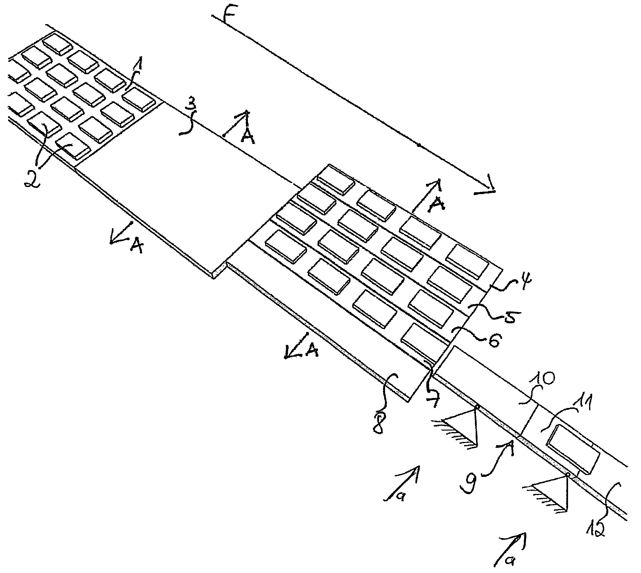
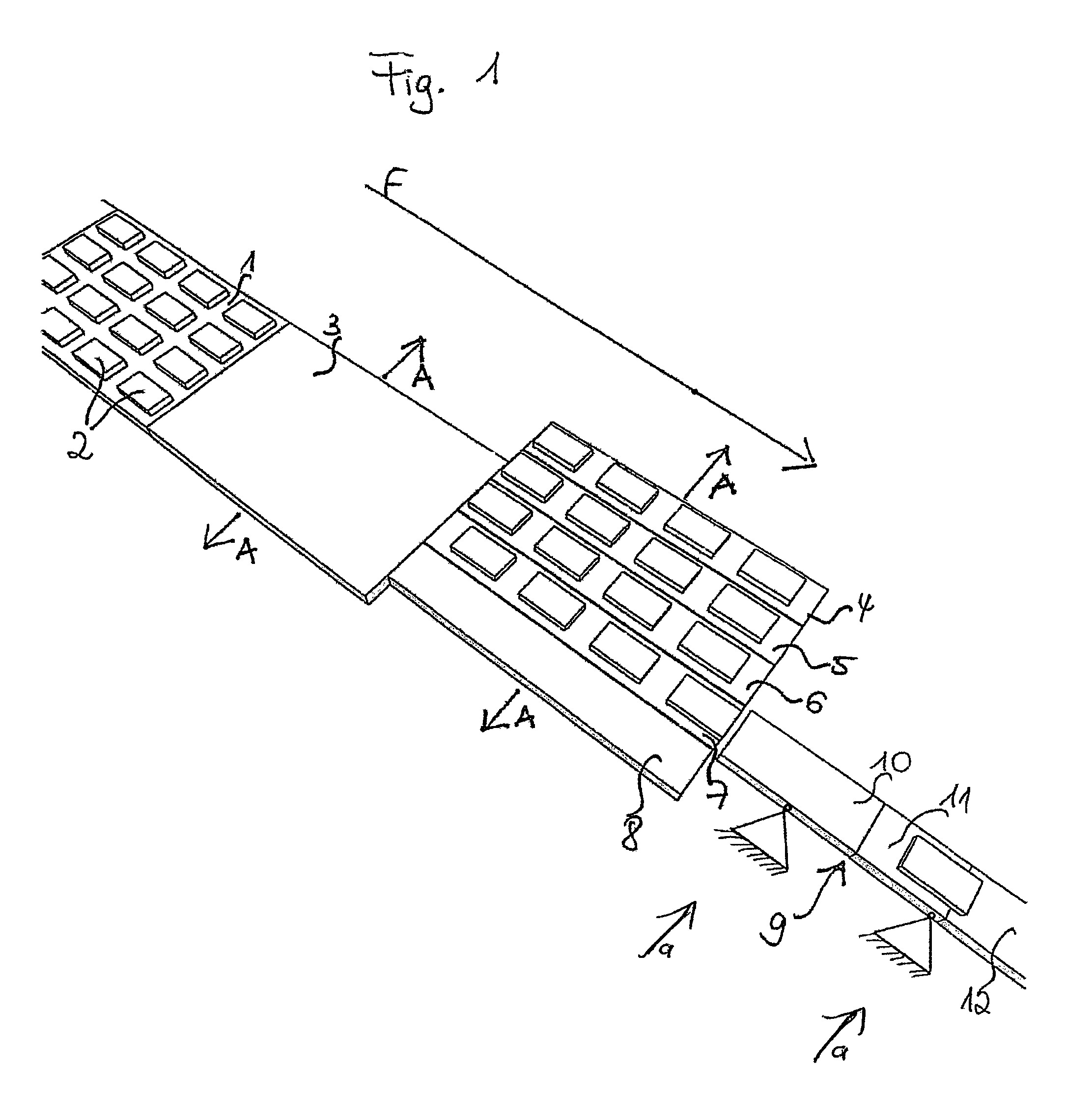
[0014]In particular an at least n-track intermediate conveyor is arranged between the n+1 parallel individual conveyors and the n-track conveying section and can be moved—as also the individual conveyors—at right angles to the conveying direction in the conveying plane. This intermediate conveyor is preferably configured for the reception of n*m separated products. The intermediate conveyor is thus in a position to take over a complete batch from the n-track conveying section in the form of a product matrix of the size n*m in order to pass the batch to n adjacent individual conveyors. The movability of the intermediate conveyor in the conveying direction makes it possible in this context to align it to the individual conveyors in the transfer process of the products such that the complete product matrix can in each case be simultaneously transferred to those individual conveyors which are no longer active in the delivery of products to the single-track conveying section following the individual conveyors. The provision of the intermediate conveyor thus makes it possible to design both that region of the n-track conveying section arranged before the intermediate conveyor in the conveying direction and the single-track conveying section such that it is in each case fixed at right angles to the conveying direction and thus does not have to be moved in that direction in any transfer processes. Only the n+1 individual conveyors and the intermediate conveyor are moved at right angles to the conveying direction. This will be explained in more detail within the framework of the description of the Figures.

Problems solved by technology

Such devices known from the prior art frequently have the disadvantage that the products have to be moved between different conveying planes, with slanted positions of the products occurring as a rule on the transfer of the products from one conveying plane into a conveying plane disposed thereabove or thereunder.
This has the result that, for example, conveyed stacks of comparatively dry slices of cheese slip in an unwanted manner, with even the complete dissolution of conveyed stacks being able to occur, which in turn has the result that such products supplied in an unordered manner cannot be processed by a packaging machine.
This then in turn causes an expensive reduction in the respective plant availability.

Method used


Image

  • Apparatus for the conveying of separated goods
  • Apparatus for the conveying of separated goods
  • Apparatus for the conveying of separated goods

Examples


Embodiment Construction

[0034]FIG. 1 shows an n-track conveying section which is here concretely made as a four-track conveying section 1 (n=4). As can be seen from FIG. 1, there is room for four tracks of products 2 on the four-track conveying section, the tracks being arranged parallel to one another.

[0035]A likewise four-track intermediate conveyor 3 whose width corresponds to the four-track conveying section 1 is adjacent to the four-track conveying section 1. There is thus room on the intermediate conveyor 3 for just as many product tracks as on the four-track conveying section 1.

[0036]A total of five (n+1) individual conveyors 4 to 8 are adjacent to the intermediate conveyor 3 of which each is configured for the reception of one product track in each case. The individual conveyors 4 to 8 extend parallel to one another such that four individual conveyors 4 to 8 arranged next to one another have the same width as the intermediate conveyor 3 or the four-track conveyor section 1.

[0037]A single-track conv...


PUM


Abstract

The invention relates to an apparatus for the conveying of homogenized products having an n-track conveying section and a single-track conveying section adjoining it, wherein at least n+1 individual conveyors extending parallel to one another in a conveying plane adjoin the end of the n-track conveying section.

Description

BACKGROUND OF THE INVENTION[0001]The invention relates to an apparatus for the conveying of separated goods using an n-track conveying section and a one-track conveying section adjoining it.[0002]Such apparatus are in particular known from food technology and can serve to convey products from a cutting apparatus to a packaging machine. If the cutting apparatus is designed as a dual or four-fold slicer, the sliced products are supplied on two tracks or on four tracks. Since many packaging machines, in particular e.g. tubular bag machines, are only suitable to process products supplied on one track, it is necessary to provide suitable devices between the cutting apparatus and the packaging machine which combine the products supplied from the cutting apparatus on multiple tracks onto a single-track conveying section.[0003]Such devices known from the prior art frequently have the disadvantage that the products have to be moved between different conveying planes, with slanted positions o...

Claims


Application Information

Patent Timeline
Patent Type & Authority Patents(United States)
IPC IPC(8): B65G47/30
CPCB65G47/681B65G2201/0202
Inventor GLAS, FRANZ
Owner ALPHA ALPENLAND MASCHENBAU HAIN & K G
Learn More