
Surface-mount crystal oscillator

a crystal oscillator and surface mount technology, applied in the direction of oscillator, printed circuit, electrical apparatus, etc., can solve the problems of separation or displacement of the metal cover 3/b>, and achieve the effect of preventing separation and displacement of the metal cover

Inactive Publication Date: 2010-05-11
NIHON DEMPA KOGYO CO LTD
View PDF4 Cites 0 Cited by
  • Summary
  • Abstract
  • Description
  • Claims
  • Application Information

AI Technical Summary

Benefits of technology

[0014]The present invention was developed in light of the above described circumstances, and an object thereof is to provide a surface-mount crystal oscillator that prevents the separation and the displacement of a metal cover from a mounting board.
[0016]According to claim 2, the plate thickness of the tip side of the protrusion is smaller than the thickness of the metal film, and one half or more of the plate thickness is buried and thrust in the film thickness. As a result, one half or more of the plate thickness of the tip side of the protrusion is buried in the thickness of the metal film, thereby making the biting of the tip side into the metal film sufficient. Accordingly, the separation and the displacement of the metal cover can be securely prevented.
[0017]According to claim 3, the metal cover is made harder than the metal film of the mounting board. As a result, the metal cover becomes harder than the metal film, thereby making it easy to thrust the tip side of the protrusion.
[0019]According to claim 5, the tip side of the protrusion is pressed and thrust in a horizontal direction in the metal film provided in the groove. As a result, the tip side of the protrusion can be securely thrust in the metal film.
[0020]According to claim 6, the outer bottom of the mounting board has external terminals, which are bonded to a set board with solder reflow. This prevents the displacement and the separation of the metal cover at the time of solder reflow of the surface-mount oscillator.
[0021]With such a configuration, the tips of the protrusions at both ends, which are provided in the protruding parts of the metal cover, are made to bite into the metal film, whereby the separation and the displacement of the metal cover can be prevented, for example, if solder melts at the time of mounting on a set board. In this case, the tips of the protrusions are thrust in the metal film, for example, by being pressed with a jig, etc. from both side faces after being inserted in the grooves of the mounting board 1.

Problems solved by technology

However, the surface-mount oscillator having the above described configuration has a problem that the metal cover 3 is separated or displaced due to the melting of also solder coated on the grooves 4b at both sides in the longitudinal direction at the time of user's mounting with solder reflow.
This problem conspicuously occurs, for example, when a user mounts surface-mount components on a set board the both surfaces of which are used for mounting.
Namely, this problem is caused, for example, by an upside-down surface-mount oscillator that is beforehand provided on one surface of a set board, which is then reversed when other surface-mount components are solder-reflowed on another surface.
Namely, this problem occurs due to the low elastic force of the protrusions 7 of the protruding parts 8 in the surface-mount oscillator.

Method used


Image

  • Surface-mount crystal oscillator
  • Surface-mount crystal oscillator
  • Surface-mount crystal oscillator

Examples


Embodiment Construction

[0027]A preferred embodiment according to the present invention is described in detail below with reference to the drawings.

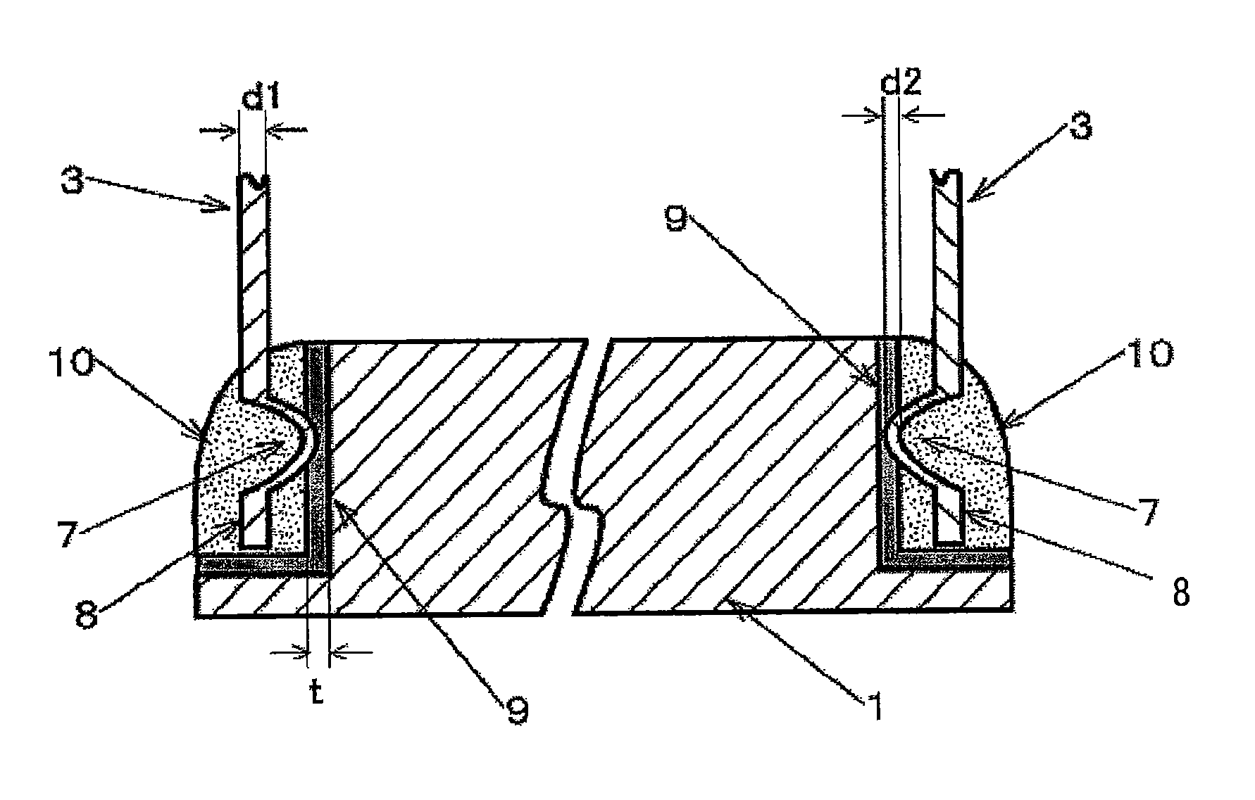
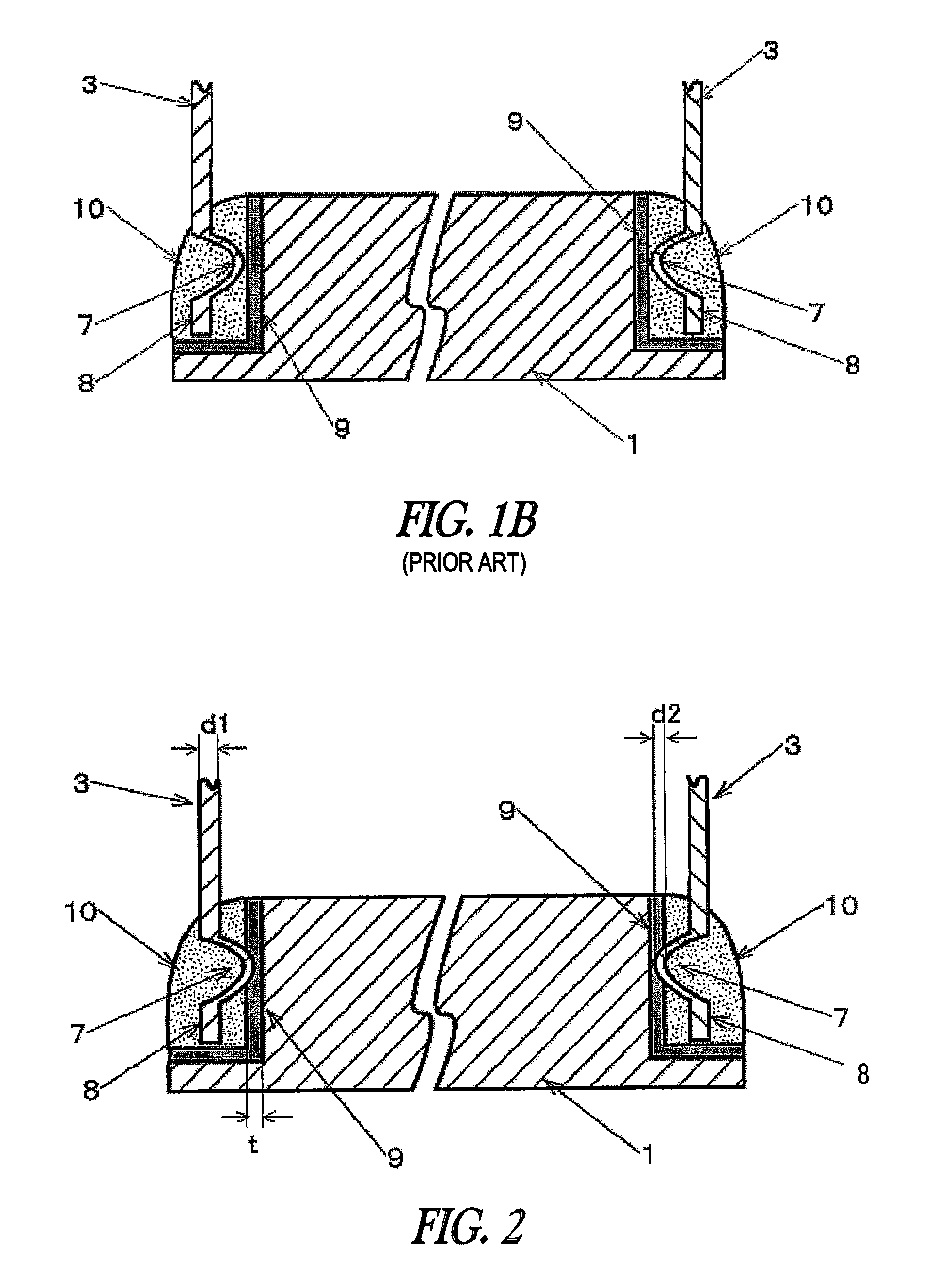
[0028]FIG. 2 is an enlarged cross-sectional view showing a portion of both ends of a surface-mount crystal oscillator (surface-mount oscillator) according to a preferred embodiment of the present invention. The same constituent elements as those shown in FIG. 1 are denoted with the same reference numerals, and their descriptions are simplified or omitted.

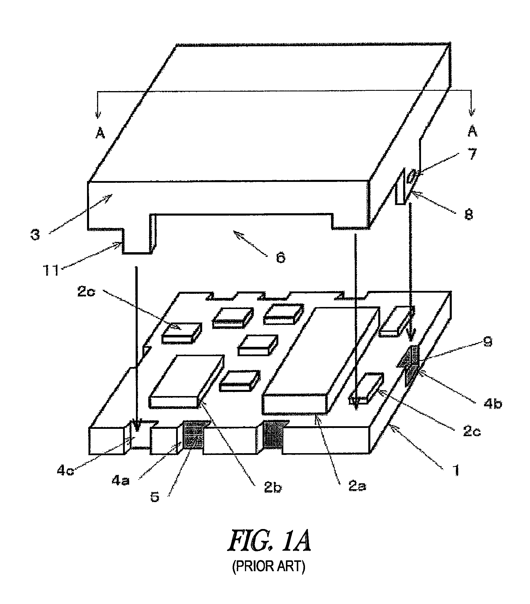
[0029]As described above, the surface-mount oscillator has a configuration where a crystal unit 2a, an IC 2b, and other circuit elements 2c are arranged on a mounting board 1 on which external terminals 4 are provided, and the mounting board 1 is covered with a metal cover 3. For the metal cover 3, its protruding parts 8, which have a protrusion 7 on an inner face and are provided at both ends in the longitudinal direction, are elastically inserted in grooves 4b provided on both side faces in the longitudinal d...


PUM


Abstract

The crystal oscillator has a configuration where circuit elements including a crystal unit are arranged on a mounting board comprising external terminals, opening end faces of a concave metal cover are made to touch the surface of the mounting board, clearances from the opening end faces are comprised in the central regions at both ends in the width direction of the metal cover, protruding parts, which extend from the opening end faces and have a protrusion on an inner face, are comprised at both ends in the longitudinal direction of the metal cover, and each of the protruding parts is elastically inserted in a groove provided on both side faces in the longitudinal direction of the mounting board 1 and bonded by solder, wherein the tip side of each protrusion is thrust and bites into a metal film provided in the groove.

Description

RELATED APPLICATION[0001]This application claims priority under 35 U.S.C. 119 to Japanese Patent Application No. 2006-355483 filed Dec. 28, 2006, which application is incorporated herein by reference and made a part hereof.BACKGROUND OF THE INVENTION[0002]1. Field of the Invention[0003]The present invention relates to a technique of a crystal oscillator composed of discrete elements, and more particularly, to a technique for preventing a metal cover, which is used for a surface-mount oscillator of a voltage control type, from separating at the time of solder reflow.[0004]2. Description of the Related Art[0005]In recent years, a surface-mount crystal oscillator (surface-mount oscillator) of a voltage control type has been incorporated into various types of electronic appliances, for example, as a reference frequency source of a PLL circuit, since its oscillation frequency in response to a control voltage is stable owing to a crystal unit.[0006]FIGS. 1A and 1B are schematic diagrams e...

Claims


Application Information

Patent Timeline
Patent Type & Authority Patents(United States)
IPC IPC(8): H03B1/00
CPCH05K3/3405H05K3/403H05K2201/09181H05K2201/10371H05K2201/1059
Inventor NAGAUSHI, HIDEO
Owner NIHON DEMPA KOGYO CO LTD
Learn More