
Optimizing tape speed for a sync operation

a tape speed and sync technology, applied in the direction of data recording, carrier speed control/regulation/indication, instruments, etc., can solve the problems of performance penalty, tape drive does not know whether the host will issue another sync command, and tape drive does not select the optimal tape speed

Inactive Publication Date: 2010-05-04
IBM CORP
View PDF15 Cites 25 Cited by
  • Summary
  • Abstract
  • Description
  • Claims
  • Application Information

AI Technical Summary

Benefits of technology

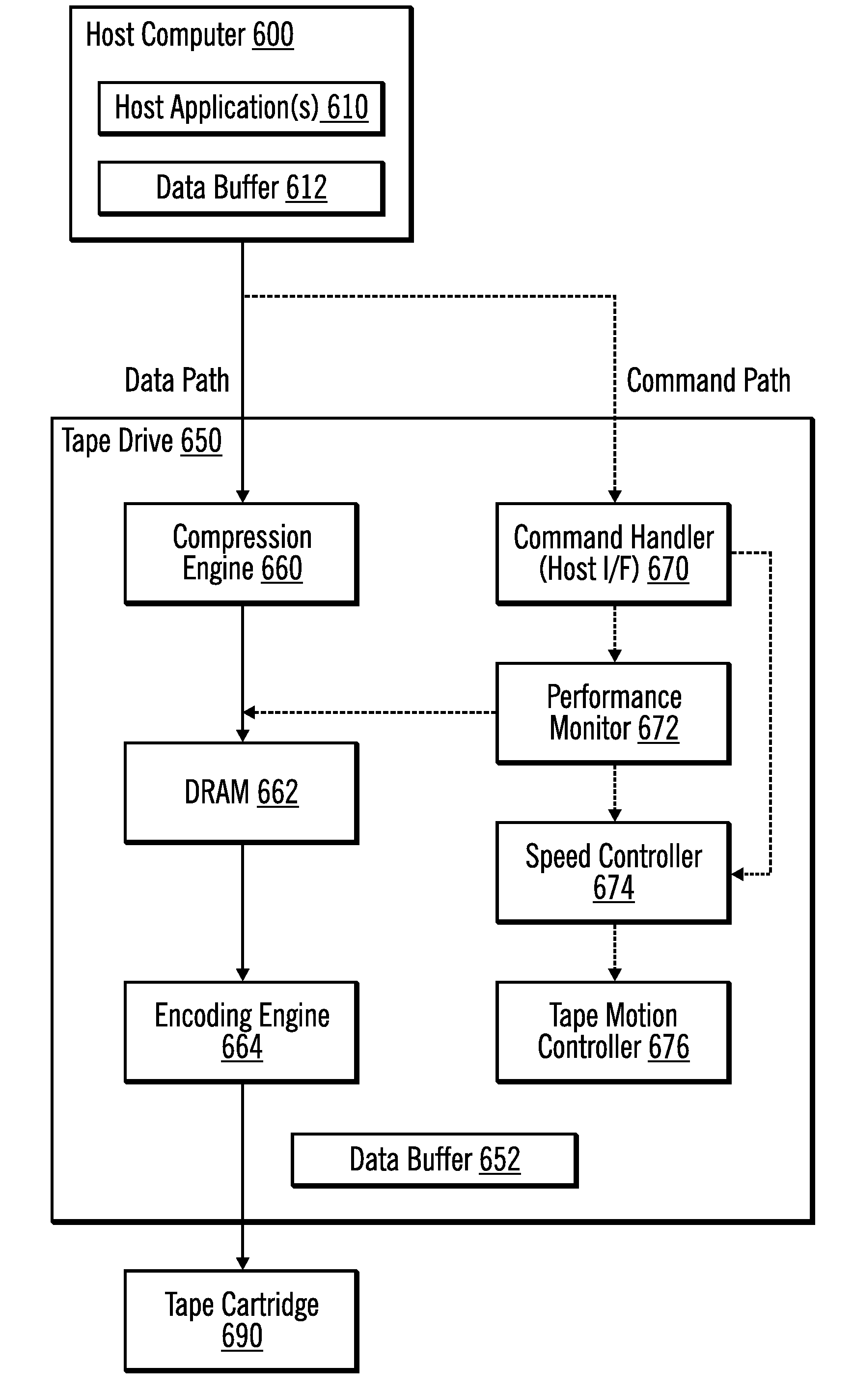
The patent describes a method, computer program product, and system for determining the speed of a tape when a sync command is received. This is done by calculating the average size of transactions and the average speed at which the host transfer rate is able to transfer data. By using this information, data can be written to the tape at the determined speed. The technical effect of this patent is to improve the speed and efficiency of writing data to tape cartridges.

Problems solved by technology

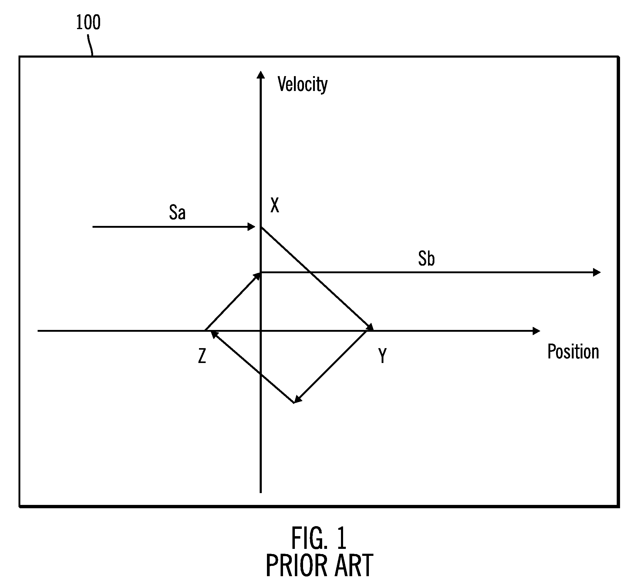
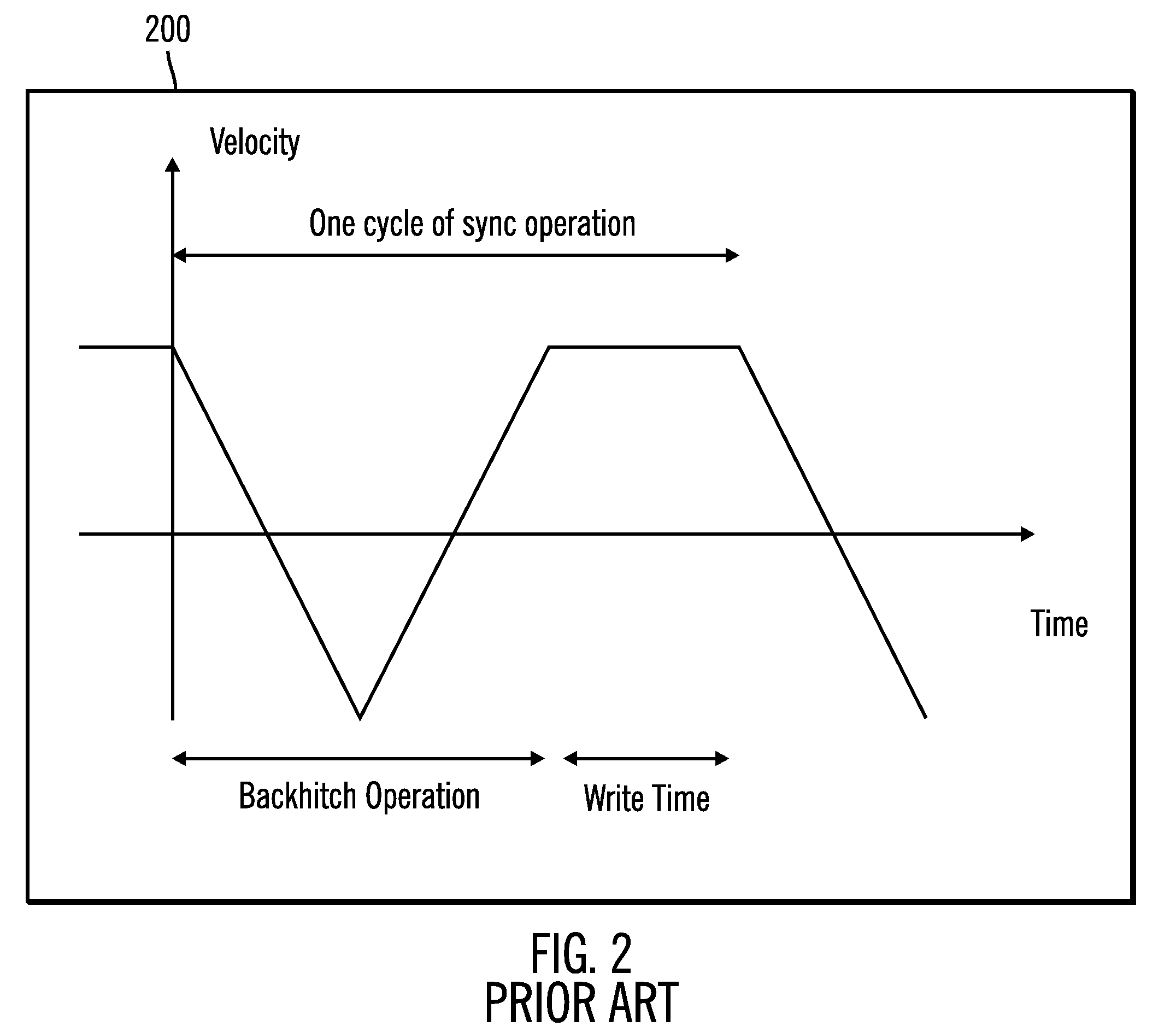
Because the tape drive cannot write the received data in backhitch motion, the backhitch motion causes a performance penalty if the host application issues many sync commands.
If the transaction size is not small, there are two problems to address.
With the first problem, when the tape drive is doing a backhitch, the tape drive does not know whether the host will issue another sync command or not.
Therefore, the tape drive does not select an optimal tape speed for the next sync operation at this time.
If the tape drive waits to write (e.g., to check whether the host might issue the sync command later) until the sync command is received, the waiting time leads to poor performance.
With the second problem, if the host transfer rate is slow, the backhitch happens in the middle of a write operation before the sync command because the buffer in the tape drive becomes empty in the middle of the write operation.

Method used


Image

  • Optimizing tape speed for a sync operation
  • Optimizing tape speed for a sync operation
  • Optimizing tape speed for a sync operation

Examples


embodiment details

Additional Embodiment Details

[0073]The described operations may be implemented as a method, computer program product or apparatus using standard programming and / or engineering techniques to produce software, firmware, hardware, or any combination thereof.

[0074]Each of the embodiments may take the form of an entirely hardware embodiment, an entirely software embodiment or an embodiment containing both hardware and software elements. The embodiments may be implemented in software, which includes but is not limited to firmware, resident software, microcode, etc.

[0075]Furthermore, the embodiments may take the form of a computer program product accessible from a computer-usable or computer-readable medium providing program code for use by or in connection with a computer or any instruction execution system. For the purposes of this description, a computer-usable or computer readable medium may be any apparatus that may contain, store, communicate, propagate, or transport the program for ...


PUM

PropertyMeasurementUnit
accelerationaaaaaaaaaa
speedaaaaaaaaaa
speedaaaaaaaaaa

Abstract

Provided are techniques for determining a tape speed for a next sync operation. A sync command is received. An average transaction size and an average host transfer rate of a set of previous sync operations are calculated. The tape speed for the next sync operation is determined using the average transaction size, the average host transfer rate, and a backhitch time. Data is written to a tape cartridge using the determined tape speed.

Description

BACKGROUND[0001]1. Field[0002]Embodiments of the invention relate to optimizing tape speed for a sync operation.[0003]2. Description of the Related Art[0004]A host computer may be coupled to a tape drive. The host computer includes cache and executes a host application. The tape drive has tape cartridges for storing data.[0005]Some commands that are received at the tape drive from the host force a sync operation, (e.g., WriteFM 0 non-immediate), and such commands may be referred to as sync commands. Also, sync operations may be performed as a result of a sync command or for other reasons implicitly by the tape drive. Thus, a sync operation may be described as the actual action of the tape drive synchronizing all the data in a data buffer to a tape cartridge. In particular, the tape drive has a data buffer. The host computer sends data in its data buffer to the tape drive, and this data is stored in the data buffer at the tape drive. The sync operation writes the data in the tape dri...

Claims


Application Information

Patent Timeline
Patent Type & Authority Patents(United States)
IPC IPC(8): G11B15/46
CPCG11B15/4733G11B15/4676
Inventor ITAGAKI, HIROSHIKARP, JAMES MITCHELLKATAGIRI, TAKASHI
Owner IBM CORP
Learn More