Lens barrel and imaging apparatus

a technology of imaging apparatus and lens barrel, which is applied in the field of lenses barrel, can solve the problems of troublesome manipulation, and damage to the lens, so as to reduce the trouble of using the imaging apparatus and reduce the deterioration of optical performan

Inactive Publication Date: 2010-05-04
CANON KK
View PDF5 Cites 0 Cited by
  • Summary
  • Abstract
  • Description
  • Claims
  • Application Information

AI Technical Summary

Benefits of technology

[0009]The present invention is directed to a lens barrel capable of decreasing deterioration of optical performance as well as decreasing trouble in using an imaging apparatus, and further capable of preventing the lens barrel from increasing in size in a radial direction, and to an imaging apparatus with the lens barrel.

Problems solved by technology

In a lens barrel with an optical system including a plurality of optical units, such as a zoom lens, inclinations of the optical units with respect to an optical axis may cause a deterioration of optical performance.
The lens barrel as discussed in Japanese Patent Application Laid-Open No. 2005-173413, however, includes no protection member that protects a lens under a condition that an imaging apparatus is stored, such that the lens may be damaged, get dusty or be stained on a lens surface thereof.
While there is one in which a cover member that covers a surface of the lens facing to an object side is fit into a lens barrel to protect the lens during a storage state of the imaging apparatus, manipulation is troublesome since a user is required to remove the cover member having fit into the lens barrel when the user uses the imaging apparatus.
Further, the user is required to keep the removed cover member or to connect the cover member to the imaging apparatus with a string or the like, such that managing the removed cover member is troublesome.

Method used


Image

  • Lens barrel and imaging apparatus
  • Lens barrel and imaging apparatus
  • Lens barrel and imaging apparatus

Examples


Embodiment Construction

[0023]Various exemplary embodiments, features, and aspects of the invention will be described in detail below with reference to the accompanying drawings.

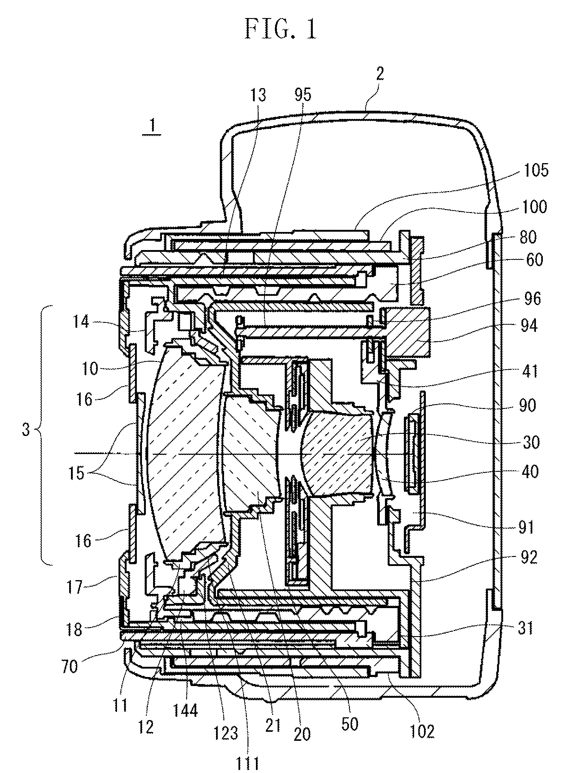
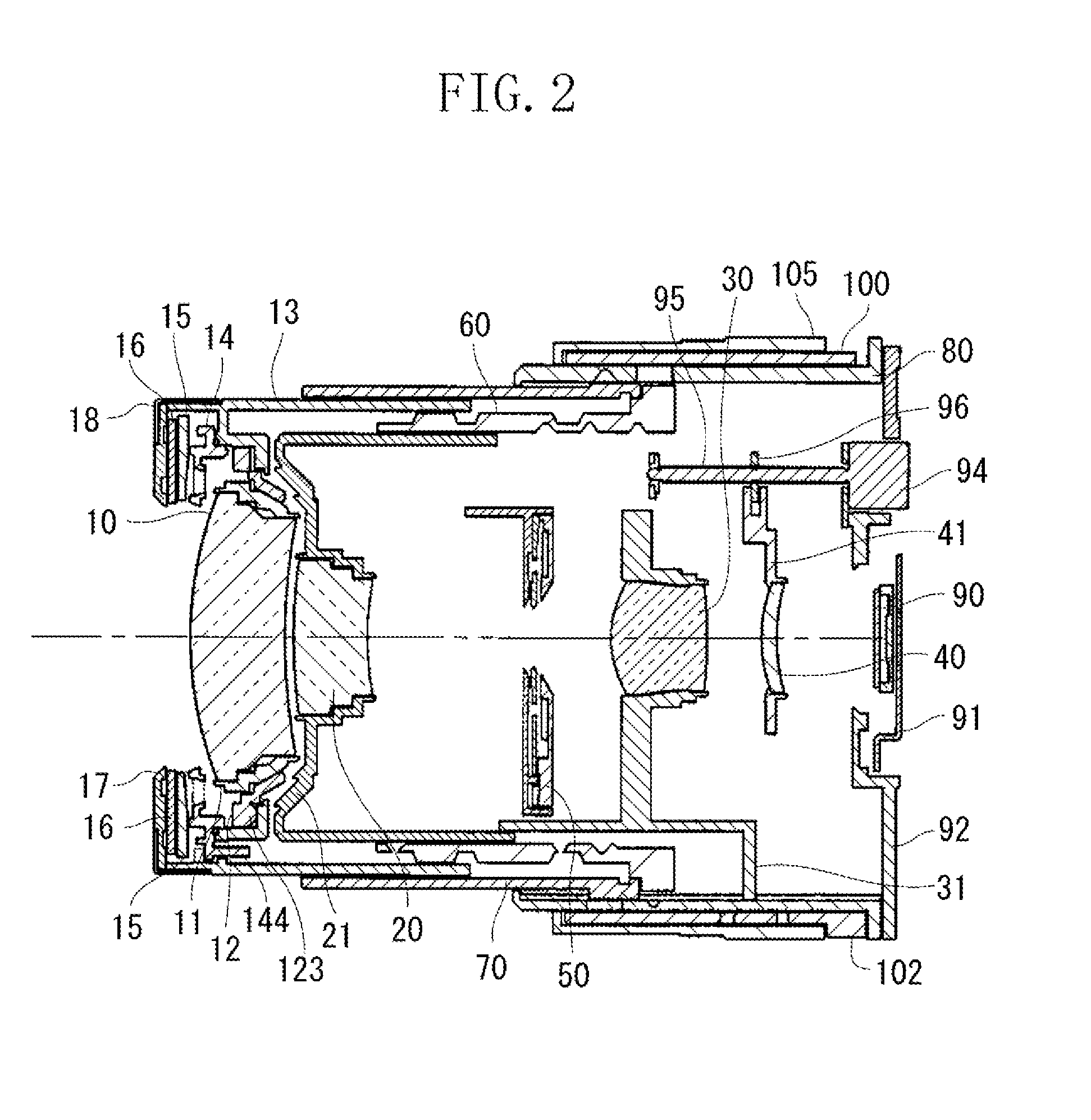
[0024]FIG. 1 is a cross sectional view of a camera with a lens barrel (in a retracted state) according to an exemplary embodiment of the present invention. FIG. 2 is a cross sectional view of the lens barrel illustrated in FIG. 1 in a wide-angle state. FIG. 3 is a cross sectional view of the lens barrel illustrated in FIG. 1 in a telephoto state.

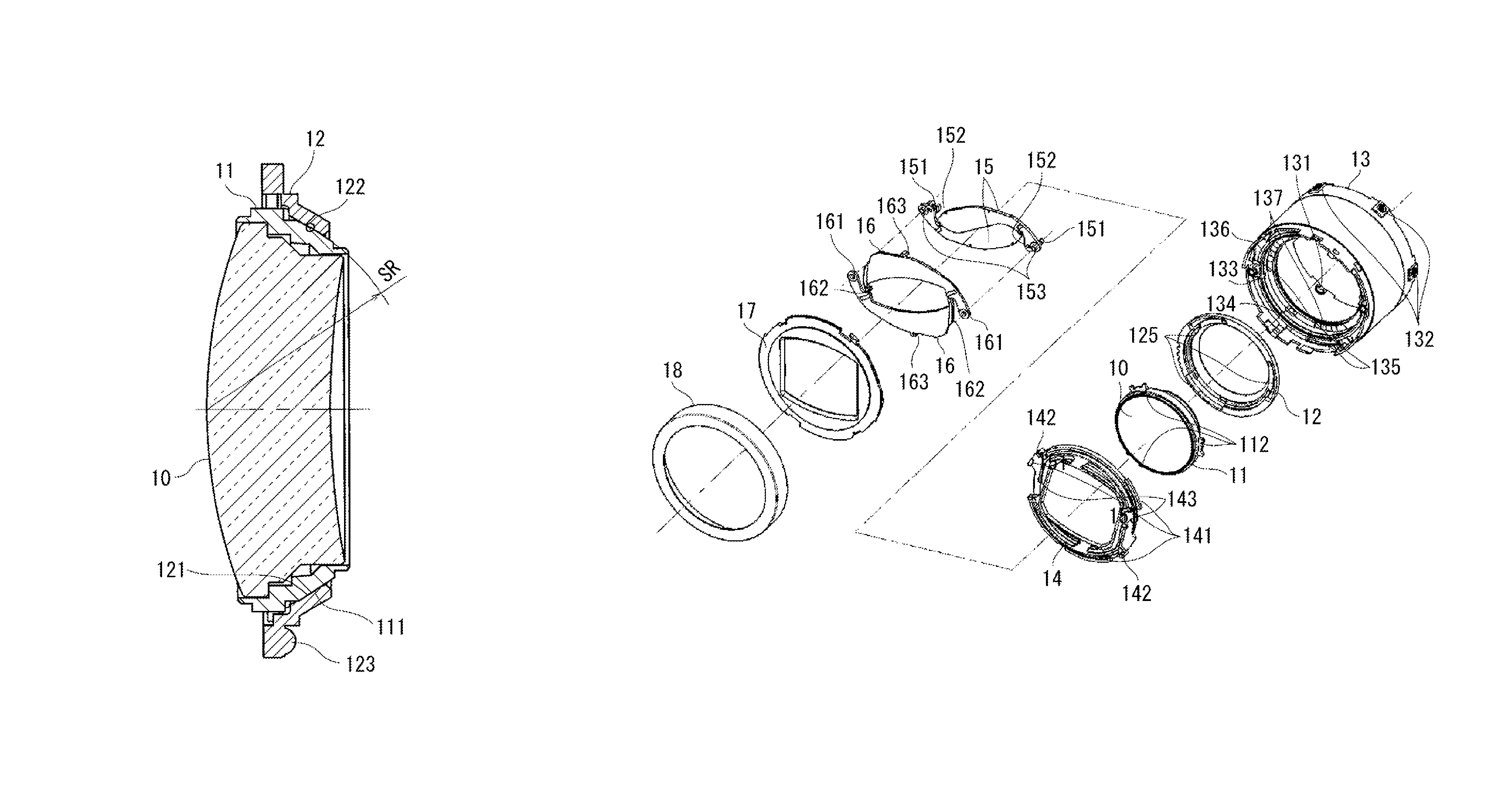
[0025]As illustrated in FIG. 1, the camera (imaging apparatus) 1 includes a camera body 2, which holds a lens barrel 3. The lens barrel 3 includes a four-unit optical system. The four-unit optical system includes a first lens unit 10, a second lens unit 20, a third lens unit 30, and a fourth lens unit 40, which are arranged from an object side to an image plane side in this order.

[0026]The first lens unit 10 is held integrally with a first lens unit holder (first holding member) 11. The fir...


PUM


Abstract

A lens barrel includes a first holding member configured to hold a lens, a second holding member configured to hold the first holding member, a protection member located at an object side of the lens in an openable and closable manner and configured to protect the lens when in a closed state, and a drive member configured to open and close the protection member. The first holding member includes an adjustment surface configured to support the first holding member rotatable with respect to the second holding member around a point located on an optical axis of the lens. The drive member is located such that the drive member overlaps the first holding member as viewed from an optical axis direction of the lens.

Description

BACKGROUND OF THE INVENTION[0001]1. Field of the Invention[0002]The present invention relates to a lens barrel having a lens adjustment mechanism and a lens protection function, and an imaging apparatus with the lens barrel.[0003]2. Description of the Related Art[0004]In a lens barrel with an optical system including a plurality of optical units, such as a zoom lens, inclinations of the optical units with respect to an optical axis may cause a deterioration of optical performance. In view of the above, in order to decrease a deterioration of optical performance, such a lens barrel that has an inclination adjustment mechanism that adjusts an inclination of, for example, a first optical unit has been discussed in Japanese Patent Application Laid-Open No. 2005-173413.[0005]The lens barrel as discussed in Japanese Patent Application Laid-Open No. 2005-173413, however, includes no protection member that protects a lens under a condition that an imaging apparatus is stored, such that the ...

Claims


Application Information

Patent Timeline
Patent Type & Authority Patents(United States)
IPC IPC(8): G02B15/14G02B7/02
CPCG02B7/08
Inventor KOBAYASHI, FUTOSHI
Owner CANON KK
Why Eureka
Try Eureka