
Rowing oar system with articulating handle

a technology of oars and handles, applied in waterborne vessels, marine propulsion, boat construction, etc., can solve the problems of reducing reducing speed, and reducing stroke ergonomics, so as to increase stroke length and power, and increase effective stroke length

Inactive Publication Date: 2010-05-04
HORAN RICHARD +1
View PDF4 Cites 9 Cited by
  • Summary
  • Abstract
  • Description
  • Claims
  • Application Information

AI Technical Summary

Benefits of technology

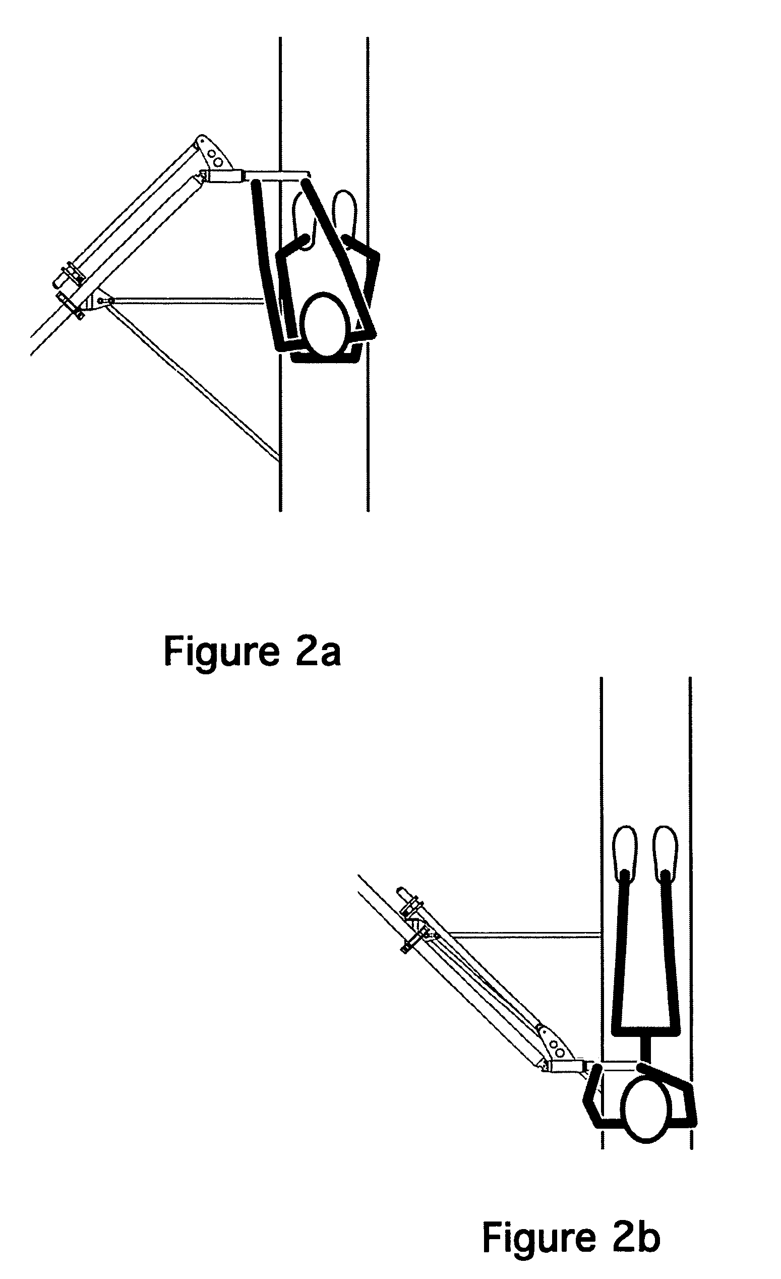
[0010]The instant invention overcomes all of the above-mentioned problems by keeping the handle perpendicular to the shell at every point in the stroke. By using this structure the length of the stroke is increased as the end of the handle is now closer to the rower; power is increased as both arms can now share the work equally; the increase in effective stroke length also increases power; sweep rowers can now keep their torsos essentially straight throughout the stroke; the reduction / elimination of twisting of the rower's upper torso reduces the likelihood of lower spine and muscle injury; the new arrangement provides for more symmetric stroke and muscle development; the reduction in twisting allows the boat to move through the water with less disruption; and, the new symmetrical stroke is more similar to most ergs (training machines), thereby making off-water training more effective and relevant.
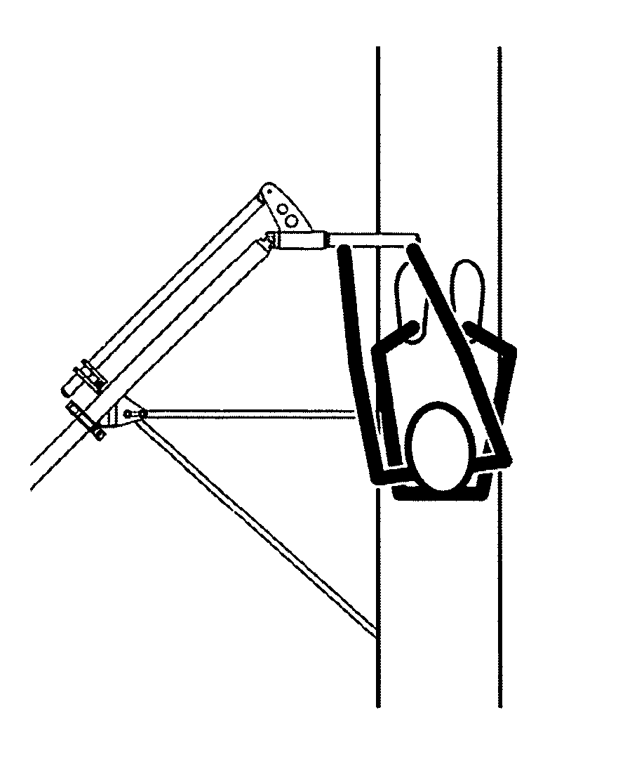
[0011]The system uses the following primary components: an oarlock assembly, which holds the main oar shaft and parallel link in line with each other while allowing them to pivot fore and aft and up and down; an oar shaft; a parallel link; and a knuckle. The knuckle positions the handle via a sleeve, and the parallel link that is positioned by a pivot on the end of an arm. Additionally, there is a universal joint between the oar shaft and the handle, in line with the parallel link pivot, that allows the blade to be feathered while keeping the handle perpendicular to the rowing shell at every point in the stroke.

Problems solved by technology

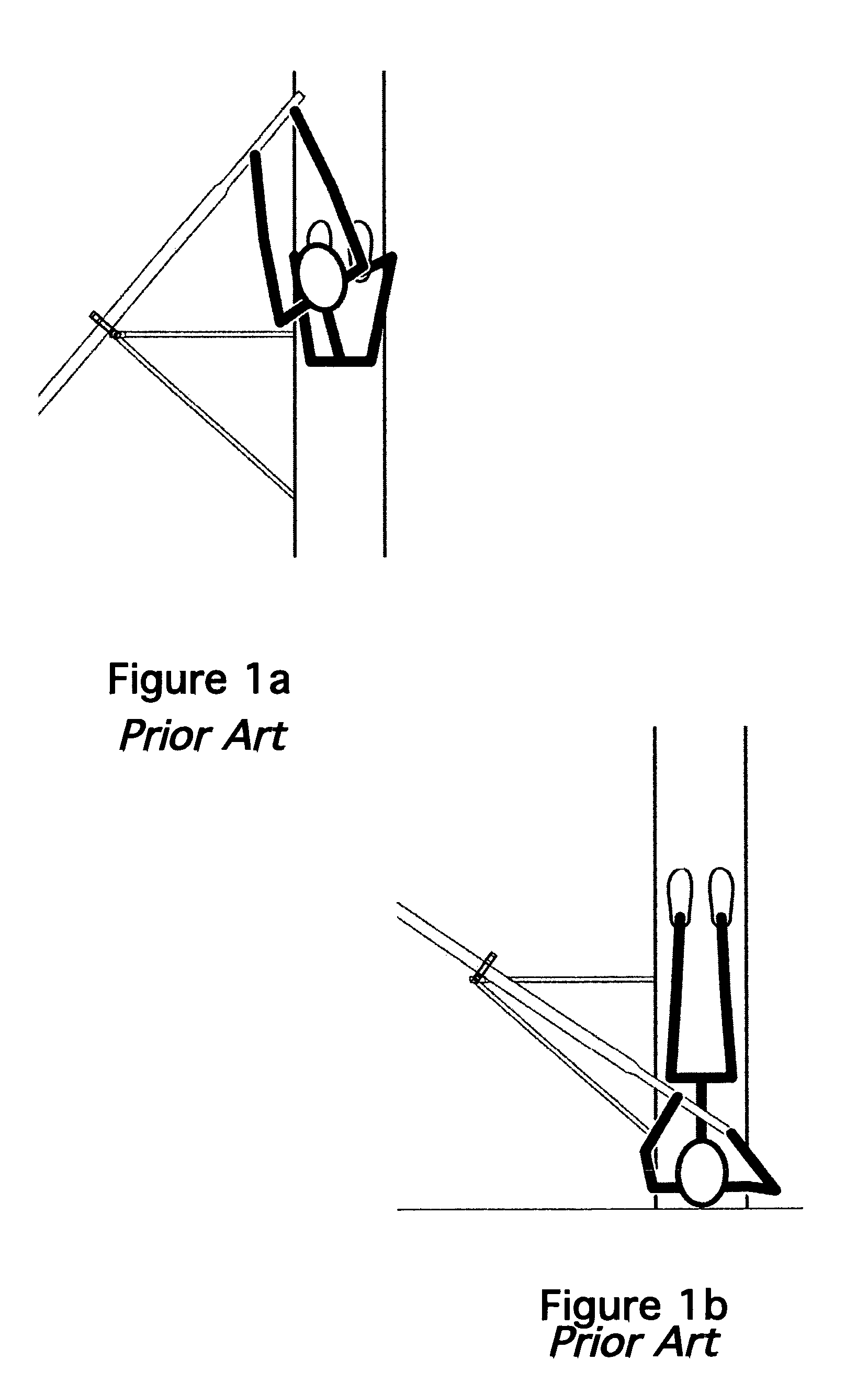
The Problem with Current Straight-Shaft (non-Articulating) Oars is that the severe angle of the oar handle at the beginning and end of the stroke results in many problems relative to boat speed and rowing ergonomics.
Some of these problems are: rowers must twist their upper torsos at the catch (beginning of stroke); the length of the stroke is limited by the length of the rowers outside arm; power is limited by the fact that the outside arm is doing most of the work; this reduction of stroke length and power reduces speed; the twisting of the rower's upper torso can cause lower spine and muscle injury' the twisting also results in the asymmetric muscle development; the twisting of the rowers disrupts the movement of the shell through the water; and, most ergs (training machines) feature a symmetrical stroke which differs greatly from the asymmetric stroke of a sweep oar, which makes off-water training less effective and relevant.

Method used


Image

  • Rowing oar system with articulating handle
  • Rowing oar system with articulating handle
  • Rowing oar system with articulating handle

Examples


Embodiment Construction

[0035]The present invention describes two alternate means to effect the functionality of the articulated handle: a single parallel link configuration and a double parallel link configuration.

[0036]Single Parallel Link Configuration

[0037]The first and preferred method is a single-parallel link configuration consisting of the main oar shaft and one parallel link. This is shown in FIG. 3. This design incorporates one parallelogram, on one side of the main oar shaft to keep the handle perpendicular to the shell at every point in the stroke.

[0038]Double Parallel Link Configuration

[0039]The second method is a double parallel link configuration consisting of the main oar shaft and two parallel links. This is shown in FIG. 4. This design incorporates two parallelograms, one on either side of the main oar shaft, to keep the handle perpendicular to the shell at every point in the stroke.

[0040]Functionality

[0041]From an operational standpoint, the improved oar is functionality is the same as t...


PUM


Abstract

An improved oar that has an oarlock assembly, which holds the main oar shaft and parallel link in line with each other while allowing them to pivot fore and aft and up and down; an oar shaft; a parallel link; and a knuckle. The knuckle positions the handle via a sleeve, and the parallel link that is positioned by a pivot on the end of an arm. Additionally, there is a universal joint between the oar shaft and the handle, in line with the parallel link pivot, that allows the blade to be feathered while keeping the handle perpendicular to the rowing shell at every point in the stroke.

Description

CROSS REFERENCE TO RELATED APPLICATIONS[0001]This application claims benefit of Provisional application 60 / 901,722 filed Feb. 15, 2007.STATEMENT REGARDING FEDERALLY SPONSORED RESEARCH AND DEVELOPMENT[0002]Not ApplicableBACKGROUND OF THE INVENTION[0003]1. Field of the Invention[0004]This invention relates to a device that keeps the oar handle perpendicular to the rowing shell at every point of the stroke and particularly to a device that keeps the oar handle perpendicular to the rowing shell at every point of the stroke by creating a parallelogram structure.[0005]2. Description of the Prior Art[0006]Presently, there are two types used in rowing. The first is called a sweep oar. Sweep oars are the larger variety and are designed so that each rower uses just one oar. Sweep shells always have even numbers of oarsman on each side of the shell. Classes include Pairs (2×), Fours (4×), and Eights (8×). Each class can include a coxswain to steer and coach.[0007]The second oar type is called ...

Claims


Application Information

Patent Timeline
Patent Type & Authority Patents(United States)
IPC IPC(8): B63H16/04B63H16/10B63H16/00
CPCB63H16/06B63H16/04
Inventor HORAN, RICHARDMILLER, JOEL
Owner HORAN RICHARD
Learn More