
Valve rotating mechanism for exhaust valves, especially of marine diesel engines

a technology of rotating mechanism and exhaust valve, which is applied in the direction of valve drives, non-mechanical valves, couplings, etc., can solve the problems of high speed of valve stem rotation and inevitable replacement of corresponding cylindrical parts, so as to prolong the useful life of the valve stem, reduce the temperature in the region, and high rotational energy

Inactive Publication Date: 2010-05-04
MARKISCHES WERK
View PDF12 Cites 0 Cited by
  • Summary
  • Abstract
  • Description
  • Claims
  • Application Information

AI Technical Summary

Benefits of technology

"The present invention provides a valve rotating mechanism for marine engines that is durable and can withstand high loads. The mechanism includes a rotary cylinder and support cylinder that are engaged with each other through helical gearing. The support cylinder is fastened to the valve housing and has an internal helical gearing that matches the opening stroke of the valve. The rotary cylinder is fastened to the valve stem via a freewheel device and is axially immovable with the pneumatic cylinder. The mechanism is designed to be effective in high-load engines and can be lubricated with hydraulic oil. The ratchet wheel of the freewheel device is disposed between the compression ring and hub, and the ratchet elements are braced by spring loading. The pneumatic cylinder contains the compressed-air cushion responsible for restoring the valve to closing direction, and the hydraulic oil being discharged simultaneously acts as lubricating oil."

Problems solved by technology

By means of the known mechanism, a relatively high speed of rotation of the valve stem can be attained during the closing operation; however, some wear of the ball tracks has to be expected, meaning that regular replacement of the corresponding cylindrical portions is inevitable.

Method used


Image

  • Valve rotating mechanism for exhaust valves, especially of marine diesel engines
  • Valve rotating mechanism for exhaust valves, especially of marine diesel engines
  • Valve rotating mechanism for exhaust valves, especially of marine diesel engines

Examples


Embodiment Construction

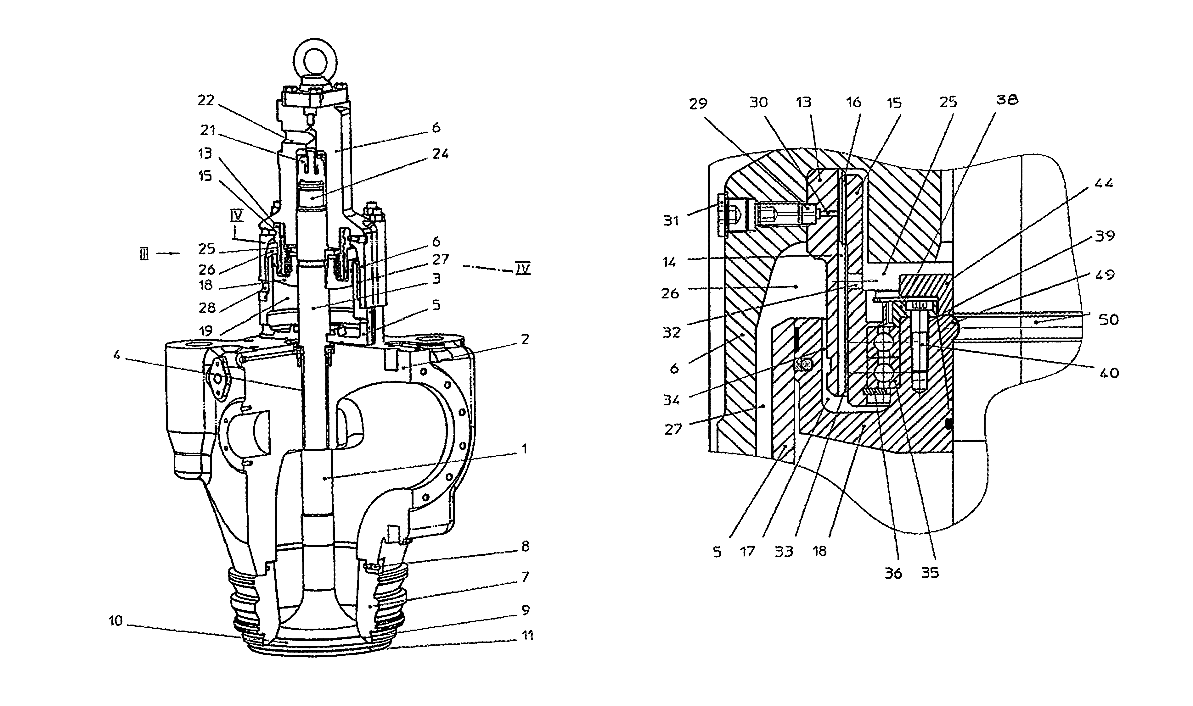
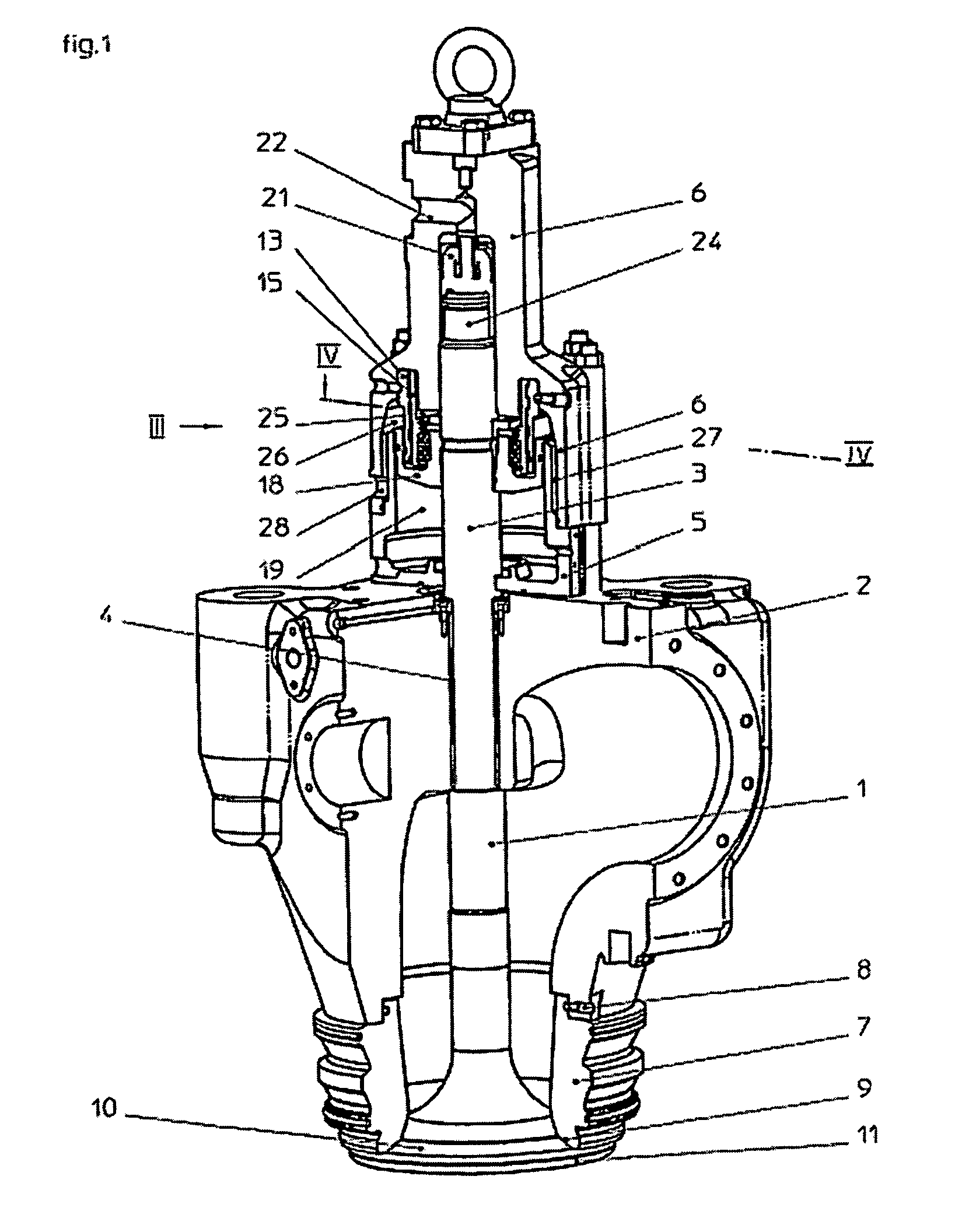
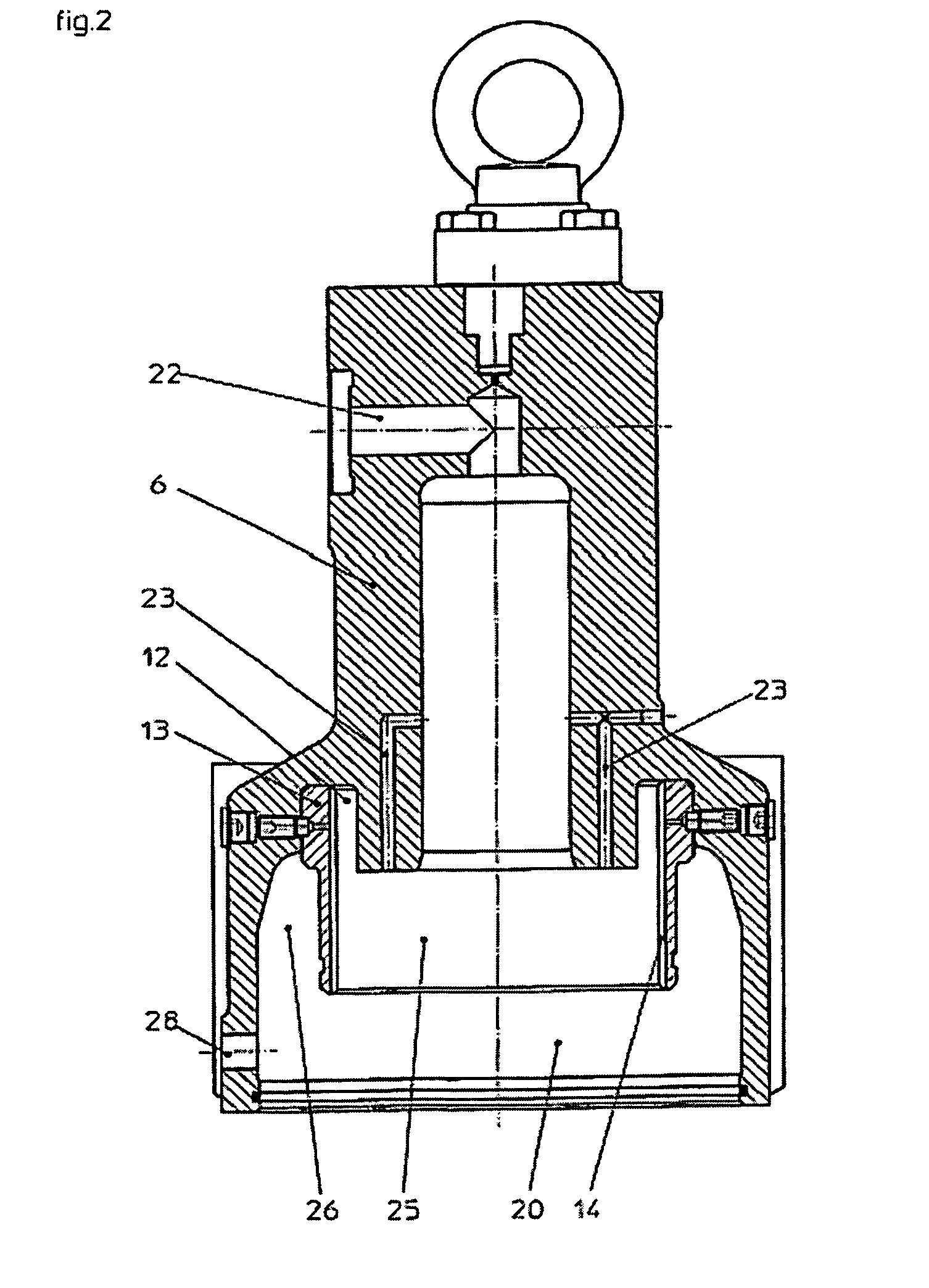
[0032]FIG. 1 shows the valve housing of a two-cycle diesel engine for a marine propulsion unit with valve stem 1 installed therein in its closed position. On a valve housing 2, in which shank 3 of valve stem 1 is mounted to rotate inside a bearing bushing 4, there is seated a pneumatic cylinder 5 and thereon a hydraulic cylinder 6. The latter is separately illustrated in the same cutaway diagram in FIG. 2. On the underside of valve housing 2 there is inserted thereinto, on the housing side, a valve seat ring 7, which is fixed there by means of bolts 8. With its open end, valve seat ring 7 forms the valve seat face on the housing side, which face comprises a material portion 9 formed by pretreatment such as hardening or weld-surfacing with hard alloy, and which cooperates with a corresponding valve seat face 10 (valve cone seat) on the upper side of valve disk 11.

[0033]In a turned recess 12 of hydraulic cylinder 6 there is fastened a support cylinder 13 by shrink-fitting onto its out...


PUM


Abstract

A valve rotating mechanism for exhaust valves, especially of marine diesel engines, which mechanism is braced in a valve housing for the valve stem (1) between an upper and a lower drive element, is linked to the lower drive element via a freewheel device, which transmits rotation of the valve stem (1) during closing movement thereof, and is also braced relative to the upper drive element via a rotary cylinder (15), which brings about rotation of the valve stem (1) through engagement with a fixed support cylinder (13). Therein the rotary cylinder (15) and support cylinder (13) are engaged with one another via a helical gearing, wherein the rotary cylinder (15) is linked to the valve stem (1) via the freewheel device and the support cylinder (13) is fastened on the housing side.

Description

CROSS-REFERENCE TO RELATED APPLICATIONS[0001]This application claims priority to International Application PCT / EP / 2004 / 004437, which was filed Apr. 27, 2004.BACKGROUND OF THE INVENTION[0002]1. Field of the Invention[0003]The invention relates to a valve rotating mechanism for exhaust valves, especially of marine diesel engines or the like, which mechanism is braced in a valve housing for the valve stem between an upper and a lower drive element, wherein it is linked to the lower drive element via a freewheel device, which allows rotation of the valve stem during closing movement thereof, and wherein it is braced relative to the upper drive element via a rotary cylinder, which brings about rotation of the valve stem through engagement with a fixed support cylinder.[0004]2. Description of the Related Art[0005]Such a valve rotating mechanism is described in German Patent 3113944. The known mechanism comprises two cylindrical portions, which are disposed concentrically relative to one a...

Claims


Application Information

Patent Timeline
Patent Type & Authority Patents(United States)
IPC IPC(8): F01L1/32F01L3/08F01L3/10F01L9/10
CPCF01L9/02F01L1/32F01L9/10
Inventor FELLMANN, HOLGER
Owner MARKISCHES WERK
Learn More