
Liquid crystal display device

a liquid crystal display and display device technology, applied in non-linear optics, instruments, optics, etc., can solve the problems of system visibility limit, pixel aperture ratio drop, etc., and achieve the effect of restrainting the downward curv

Active Publication Date: 2010-04-27
EPSON IMAGING DEVICES CORP +1
View PDF29 Cites 1 Cited by
  • Summary
  • Abstract
  • Description
  • Claims
  • Application Information

AI Technical Summary

Benefits of technology

[0014]An advantage of some aspects of the invention is to provide a liquid crystal display device in which disclination is restrained.

Problems solved by technology

However, this system has a limit in angle of visibility because of the display principle thereof.
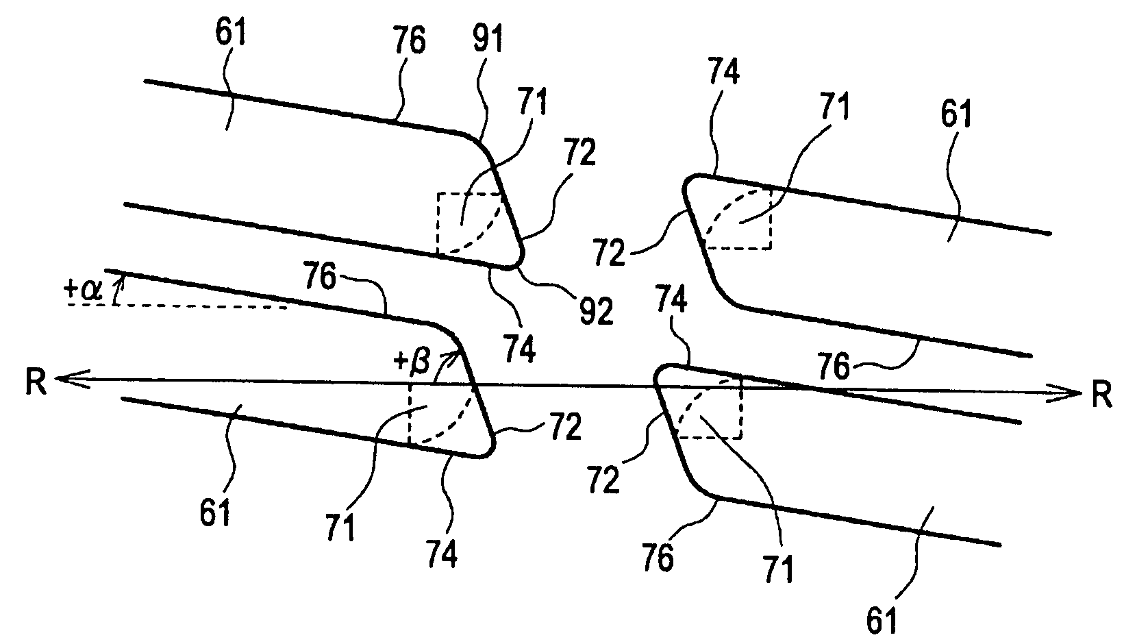
However, when forming the openings into an elongated groove shape, the edge portions at the ends of the long side are formed into a round shape or an arcuate shape in many cases due to the limit of the formation process (exposure, etching).
However, since the edge portions have a curved shape due to the limitation in exposure process, a trace of rubbing, that is, the disclination (disclination lines) is generated in the white tone.
However, this results in lowering of the aperture ratio of pixel.

Method used


Image

  • Liquid crystal display device
  • Liquid crystal display device
  • Liquid crystal display device

Examples


Embodiment Construction

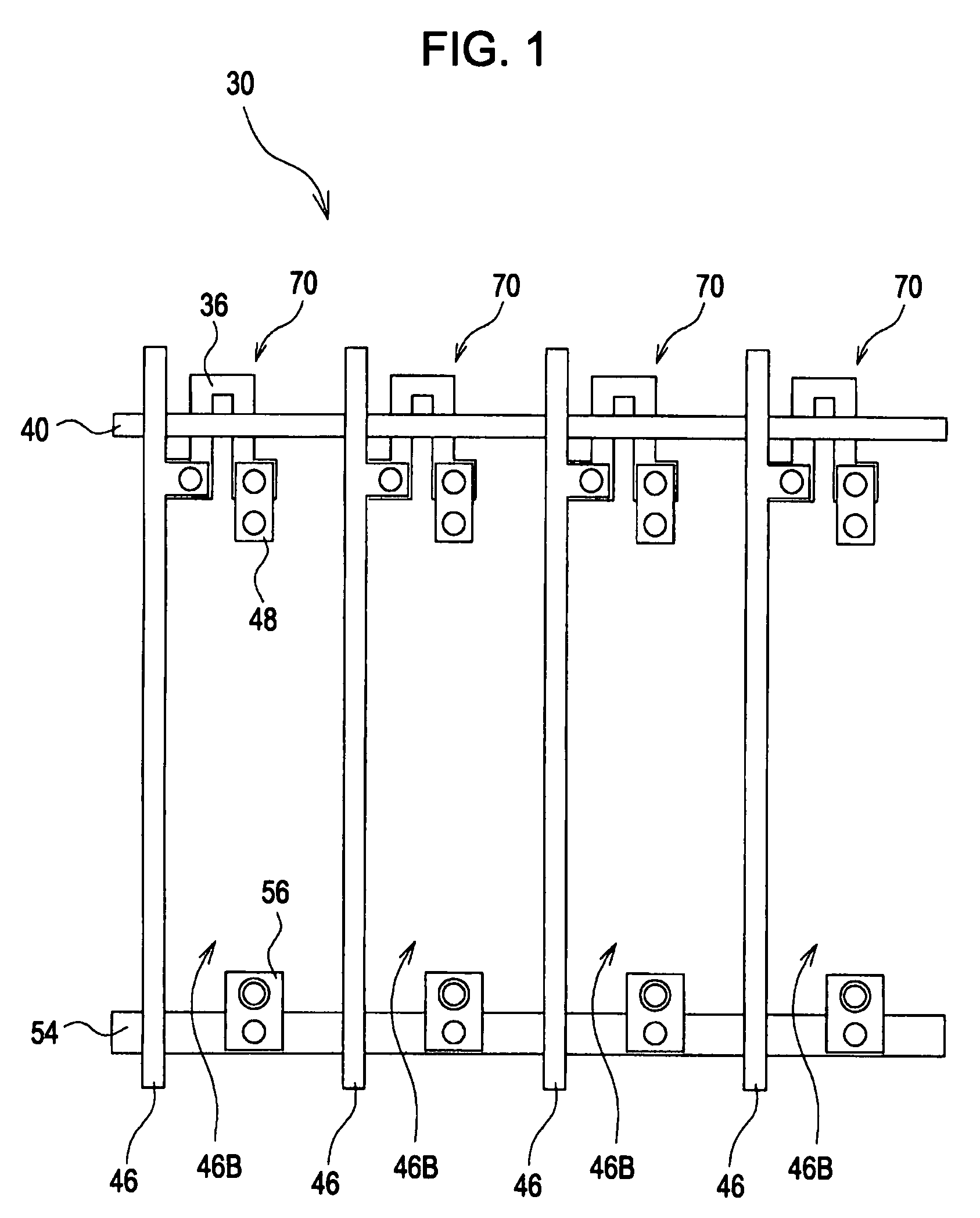
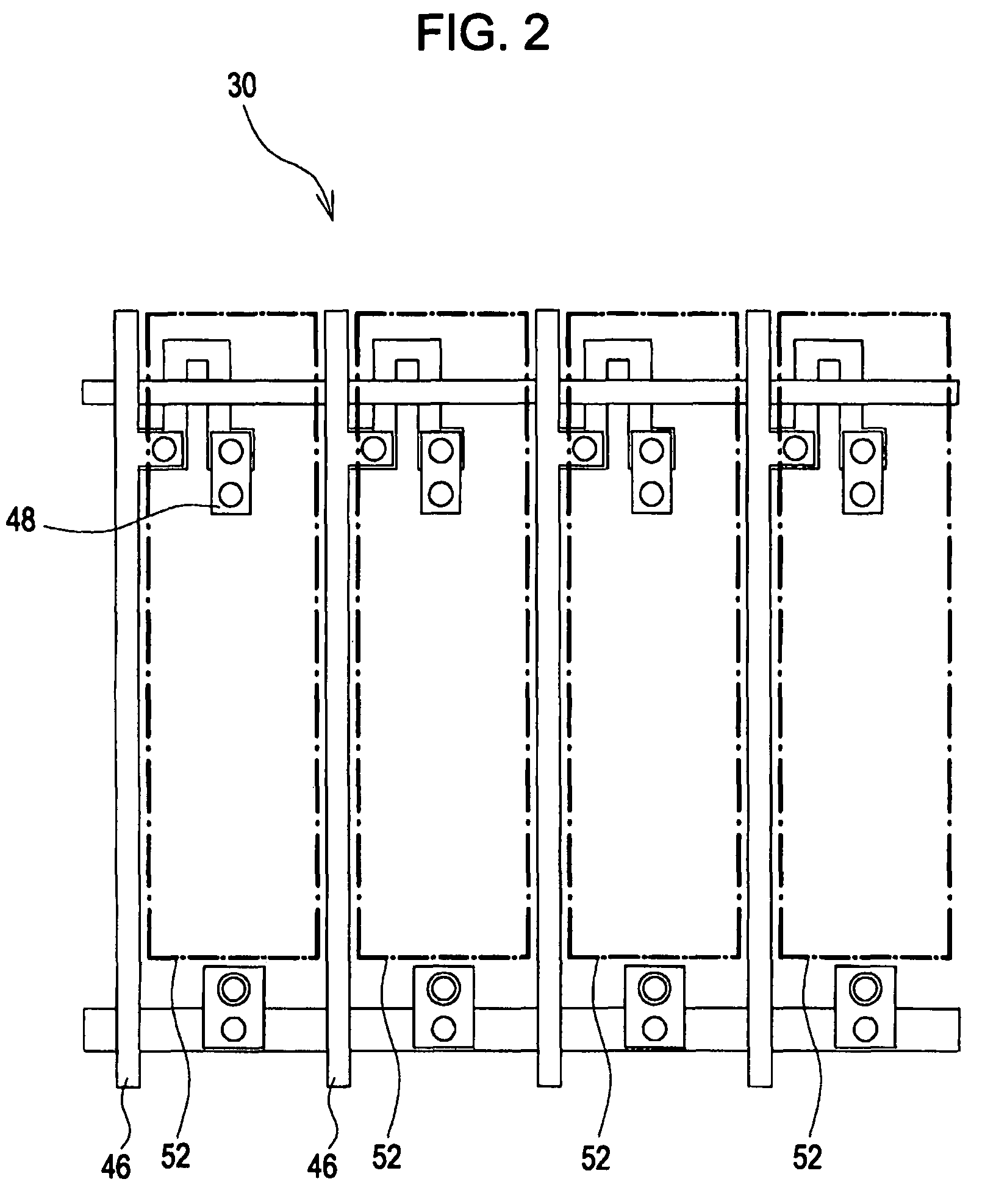
[0037]Referring now to the drawings, embodiments of the invention will be described in detail. The following description will be given about a FFS system liquid crystal display device configured to display with four colors: red (R), green (G), blue (B), and cyan (C). However, an exemplary embodiment of the invention includes a liquid crystal display device configured with three colors of R, G, and B, and also a liquid crystal display device configured simply with black and white as a matter of course. The following description will be given about the configuration of the FFS system in which a lower electrode layer is used as a pixel electrode and an upper electrode layer is used as a common electrode. However, the inverted configuration, that is, a configuration in which the lower electrode layer is used as the common electrode and the upper electrode layer is used as the pixel electrode is also applicable. In the FFS system shown below, the common electrodes are arranged separately...


PUM

PropertyMeasurementUnit
angleaaaaaaaaaa
angle of inclinationaaaaaaaaaa
angleaaaaaaaaaa

Abstract

A liquid crystal display device having an upper electrode layer and a lower electrode layer formed on an identical substrate via an insulating layer includes slits formed on the upper electrode layer for applying voltage between the upper electrode layer and the lower electrode layer and driving liquid crystal molecules. Edge portions of the slits each include a first curved portion the tangential direction of which at the edge portions with respect to the rubbing direction falls within a range from 0° to +90° and a second curved portion the tangential direction of which at the edge portions with respect to the rubbing direction falls within the range from 0° to −90°. The direction toward an acute angle subtended by the long sides of the slits with respect to the rubbing direction is the positive direction. The second curved portion is smaller than the first curved portion.

Description

CROSS-REFERENCE TO RELATED APPLICATION[0001]This application claims priority from Japanese Patent Application No. 2006-280583 filed in the Japanese Patent Office on Oct. 13, 2006, the disclosure of which is incorporated herein by reference in its entirety.BACKGROUND[0002]1. Technical Field[0003]Embodiments of the present invention relate to a liquid crystal display device and, more specifically, to a liquid crystal display device in which one of an upper electrode layer and a lower electrode layer formed on an identical substrate via an insulating layer is assigned as a common electrode layer, and the other one of the upper electrode and lower electrode is assigned as a pixel electrode layer, the upper electrode layer is formed with slits, through which voltage is applied between the upper electrode layer and the lower electrode layer for driving liquid crystal molecules.[0004]2. Related Art[0005]In the related art, TN (Twisted Nematic) system has been widely used as a display syste...

Claims


Application Information

Patent Timeline
Patent Type & Authority Patents(United States)
IPC IPC(8): G02F1/1345
CPCG02F1/133707G02F1/134363G02F2001/134372G02F1/134372G02F1/1343
Inventor SEGAWA, YASUOAOTA, MASAAKIICHIKAWA, SHINJI
Owner EPSON IMAGING DEVICES CORP
Learn More