
Dust boot with grease channel

a technology of dust boot and grease channel, which is applied in the direction of couplings, mechanical equipment, rod connections, etc., can solve the problems of low maintenance of “lube-for-life” parts, affecting sealing ability, and not having the life of “greasable” parts, so as to improve lubrication and protect against contaminants.

Active Publication Date: 2010-04-27
FEDERAL MOGUL WORLD WIDE LLC
View PDF22 Cites 23 Cited by
  • Summary
  • Abstract
  • Description
  • Claims
  • Application Information

AI Technical Summary

Benefits of technology

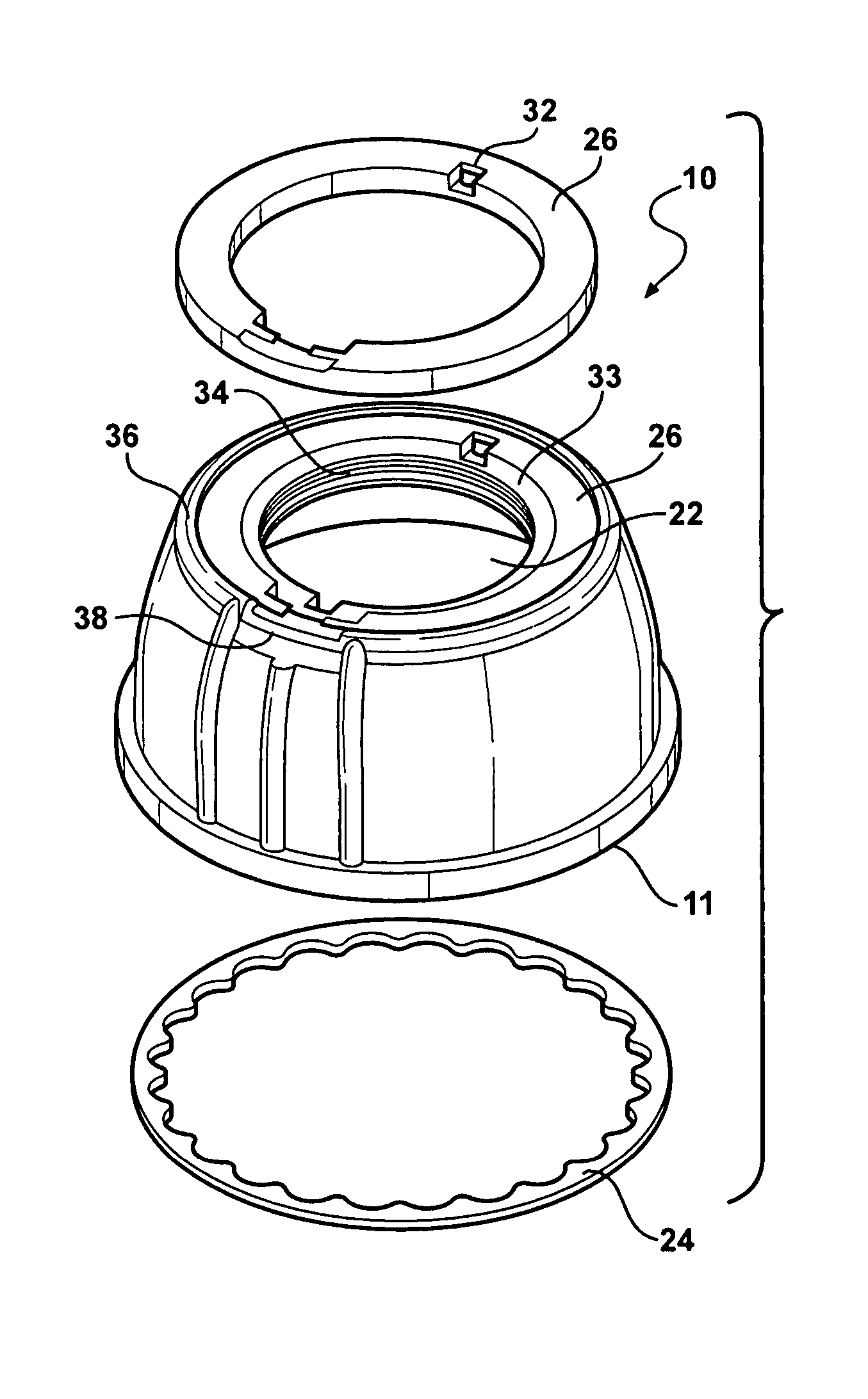
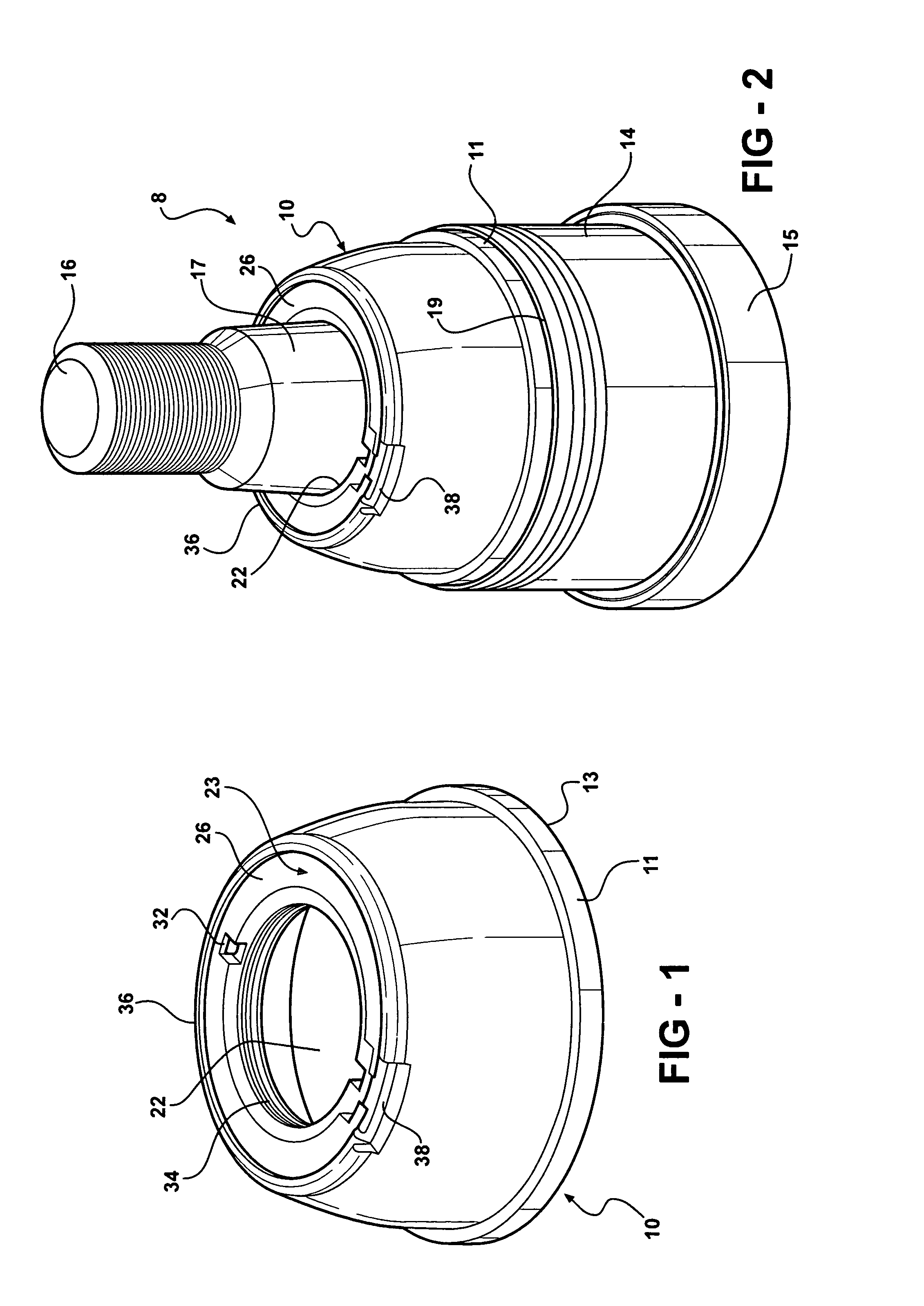
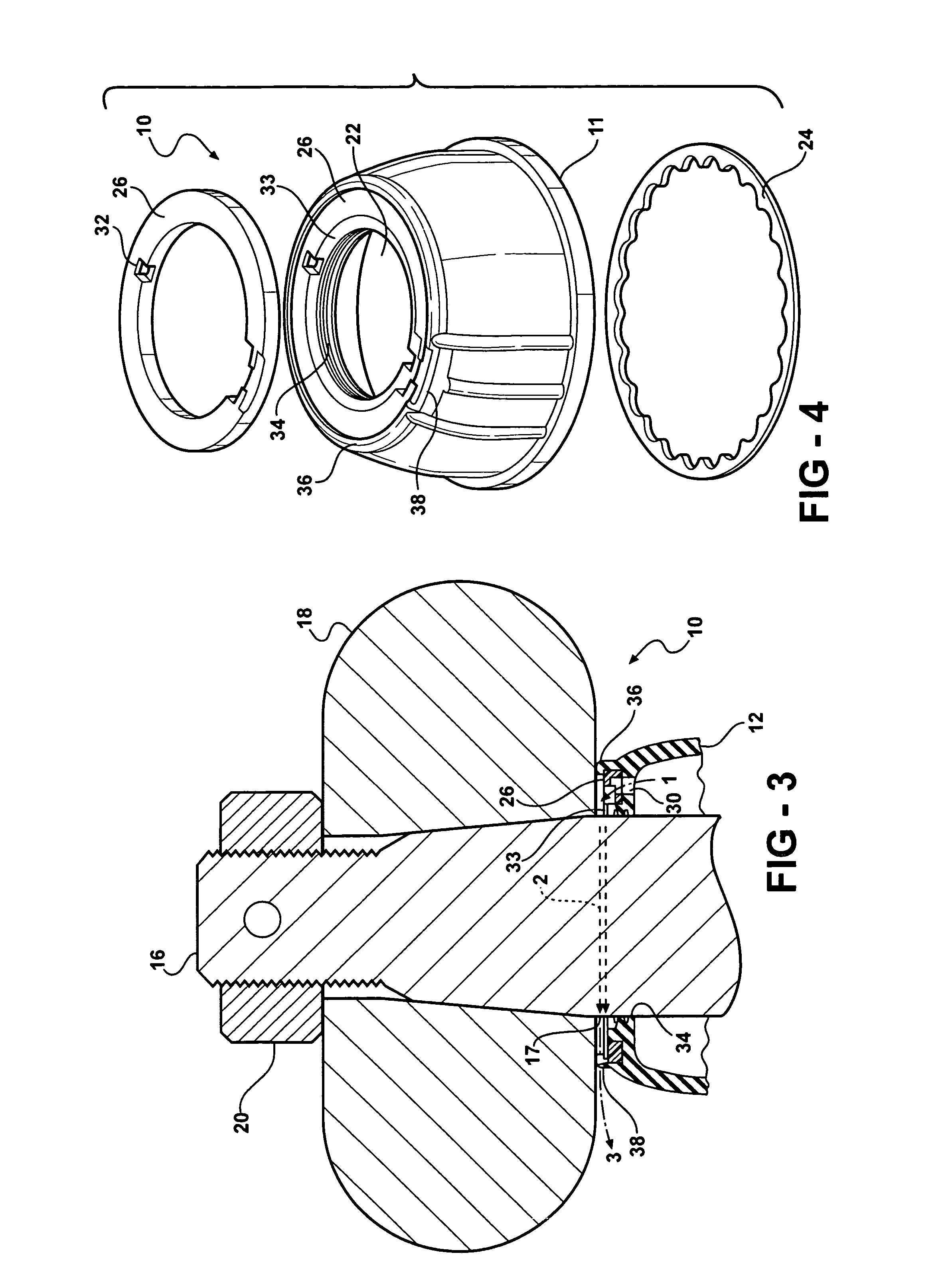
[0009]A dust boot with enhanced protection from contaminants and improved lubrication characteristic includes a dust boot body having a housing opening on one end and on an opposing end a stud opening in an upper boot wall. The boot also includes a wiping lip located on an inner face of the upper boot wall in the stud opening, a grease channel on an outer surface of the upper boot wall bounded circumferentially by a rim seal, an offset opening hole through the upper boot wall into the grease channel which is offset from the wiping lip, and a flexible flap portion of the rim seal which is spaced away from the offset opening hole.
[0014]The subject dust boot design advantageously improves greaseability and lubrication by the use of an offset hole combined with a unique circumferential grease channel. The improved design evacuates grease through an offset hole that is spaced from the stud opening. The grease is then directed through a grease channel around the small, or stud exit end, of the dust boot toward a flap where the grease exists.
[0015]Evacuating the grease through the offset hole, instead of along the moving surface of the stud, significantly reduces the chance of contamination entering the socket of the part. If contamination does get beyond the flap, it is unlikely that it will continue through the grease channel and into the offset hole. Therefore, advantageously, the risk of contamination is reduced.

Problems solved by technology

These “lube-for-life” parts are low maintenance since they are sealed, but generally do not have the life of a “greaseable” part.
The challenge in designing a dust boot for a greaseable part is that the dust boot must serve as a barrier to prevent contaminants from entering the articulating component.
The problem, therefore, with prior designs is that sealing capabilities may be compromised in order to ensure that the boot will also be able to allow grease to exit from the dust boot in a controlled manner.
Furthermore, there is a need for the stud opening of a dust boot to be lubricated as grease exits the dust boot which is not accomplished by prior designs.

Method used


Image

  • Dust boot with grease channel
  • Dust boot with grease channel
  • Dust boot with grease channel

Examples


Embodiment Construction

[0026]Referring to FIGS. 1-8C, a dust boot according to the subject invention is generally shown at 10 in FIGS. 1 and 2. A dust boot 10 is a highly resilient device typically molded into the shape of a dome or convolute. The dust boot may have other shape configurations instead of domed, including many variations of a stepped or capped cylinder, accordion-like folds or other well-known shapes. Dust Boot 10 is generally formed from an elastomer, such as natural or synthetic rubber and the like, or various plastics. A material is chosen having inherent resiliency tending to reclaim its original molded shape upon deformation although accommodating such deformation without appreciable resistance.

[0027]The body of the dust boot 10, in this example possessing a domed shape, includes a large opening 12 or housing opening 12 on a housing end 13 having a lip 11 or other feature adapted to fit tightly against the stud exit end 19 of a joint housing 14. The large opening 12 and lip 11 of the d...


PUM


Abstract

A dust boot with enhanced protection from contaminants and improved lubrication characteristic includes a dust boot body having a housing opening on one end and on an opposing end a stud opening in an upper boot wall. The boot also includes a wiping lip located on an inner face of the upper boot wall in the stud opening, a grease channel on an outer surface of the upper boot wall bounded circumferentially by a rim seal, an offset opening hole through the upper boot wall into the grease channel which is offset from the wiping lip, and a flexible flap portion of said rim seal which is spaced away from said offset opening hole. The dust boot may also include an insert made from a plastic such as nylon housed in the upper boot wall such that the offset opening hole extends through the insert. The insert may also form a portion of the grease channel. The offset opening is preferably spaced opposite the flexible flap to promote the flow of grease around the outer surface of the stud. The dust boot may be incorporated into a joint assembly by placing it in sealing engagement with a housing which holds a stud in articulating engagement.

Description

CROSS-REFERENCES TO RELATED APPLICATIONS[0001]This patent application claims priority to U.S. Provisional Patent Application Ser. No. 60 / 711,366, filed Aug. 25, 2005, which is incorporated herein by reference in its entirety.BACKGROUND OF THE INVENTION[0002]1. Field of the Invention[0003]This invention relates to a boot type seal, especially adapted for ball and socket type joints, although useful in any installation for sealing relatively articulatable, tiltable or rotatable members while automatically venting or relieving excess pressures such as might be developed by high pressure lubrication or by the accumulation of excessive amounts of lubricants.[0004]2. Related Art[0005]Nearly all original chassis equipment, such as ball joints and tie rod ends, are sealed units. These “lube-for-life” parts are low maintenance since they are sealed, but generally do not have the life of a “greaseable” part. A greaseable part may be greased periodically to replace grease which has escaped or ...

Claims


Application Information

Patent Timeline
Patent Type & Authority Patents(United States)
IPC IPC(8): F16C11/00
CPCF16D3/845F16J3/046Y10T403/32729Y10T403/31F16C11/0671
Inventor ELTERMAN, JAMESKARPMAN, ALEXANDERDOHERTY, DONALDBYRNES, THOMAS
Owner FEDERAL MOGUL WORLD WIDE LLC
Learn More