Eureka AIR delivers breakthrough ideas for toughest innovation challenges, trusted by R&D personnel around the world.

Label

a technology of labels and labels, applied in the field of labels, can solve the problems of insufficient label performance, inability to read or write information of ic labels, and greatly impede label performance, so as to avoid the danger of label substrate being erroneously cut, easy to be bent and pasted together, and easy to be ben

Active Publication Date: 2010-04-27
SATO CO LTD
View PDF21 Cites 50 Cited by
  • Summary
  • Abstract
  • Description
  • Claims
  • Application Information

AI Technical Summary

Benefits of technology

[0060]In the present invention, recording by printing using a printer can be performed on the RFID label without any interference by the unevenness or thickness of the IC tag holding part.
[0061]Furthermore, the IC tag can securely receive electromagnetic waves without being affected by the material or contents of the object [of pasting]. Moreover, by constructing the bent parts by means of perforations formed in the label substrate or narrow-width parts formed by partial narrow working of the width of the label substrate, it is easily possible to ascertain the bending locations, so that the label substrate can easily be bent and pasted together without any deviation. Furthermore, if the bent parts are constructed by means of bending lines printed on the label substrate or narrow-width parts formed by partial narrow working of the width of the label substrate, the danger of cutting away the label substrate in an erroneous position can be avoided.
[0062]Furthermore, if perforations or a slit is formed in the peeling paper either coinciding with or in the vicinity of at least one bent part of the label substrate, the label substrate can be easily bent along the bending position of the peeling paper, so that the danger that the position where the label substrate is folded back and pasted together will be mistaken can be reduced; at the same time, the danger that the label substrate will be erroneously cut away can be avoided.
[0063]Furthermore, in the pasting method of the present invention, by pasting or wrapping and pasting the label to the slender neck part of a bottle filled with a liquid in a position above the liquid level in this bottle, it is possible to receive electromagnetic waves in a favourable manner without any interference from other bottles or RFID labels; a similar effect can also be obtained by pasting the label so that the respective pasting parts straddle the edge lines of a box-shaped container.
[0064]Furthermore, the invention refers to a device for applying a label according to the invention, which comprises a folding mechanism in order to fold the attachment section and the stroke section towards each other.
[0065]In a preferred embodiment of the device, it may comprise a supporting device for holding the label prior to folding it.

Problems solved by technology

However, these latter RFID tags are generally not connected to a memory provided for storing data related to the object, since the tag is generally only calibrated to a particular resonant frequency, provided to react and trigger an alarm signal when the object with the tag passes a gate where the resonant frequency is detected.
Furthermore, though this also varies according to the frequency, electromagnetic waves are absorbed by metals and water especially in RFID in the UHF band; accordingly, if metals or water are present in the vicinity of the reader or IC tag, there may be instances in which information of the IC tag cannot be read or written.
There are also other situations where the performance of the label is not sufficient.
Depending on the composition or shape of the object on which the tag or label is affixed, the performance of the tag can be greatly impeded due to the nature of RFID and the laws of physics.
This human intervention increases the costs and chances of error, and slows down the whole identifying operation.

Method used


Image

  • Label
  • Label
  • Label

Examples


Embodiment Construction

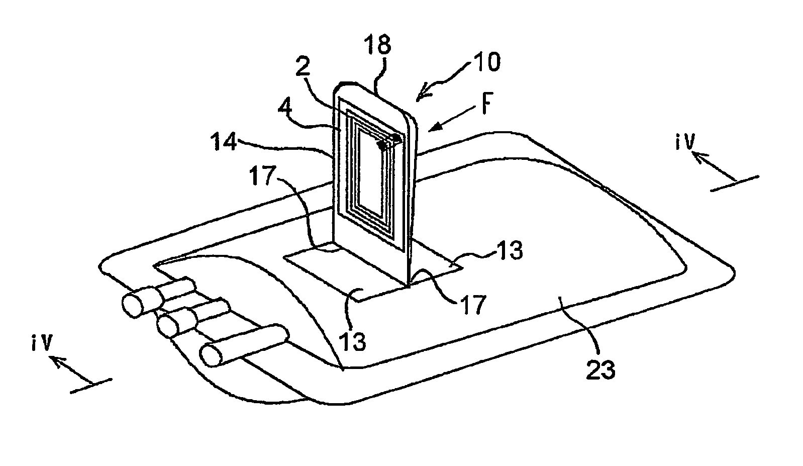
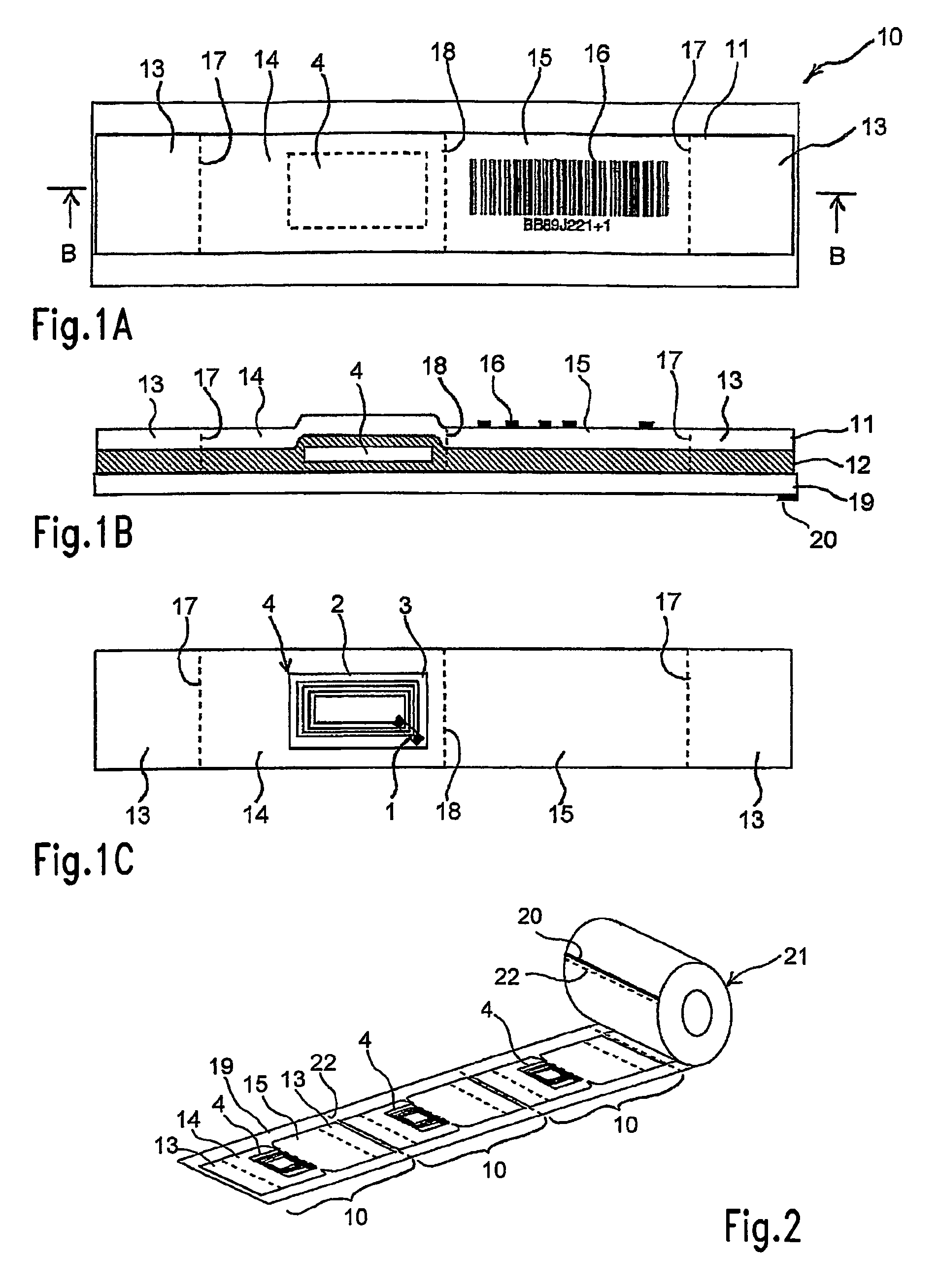
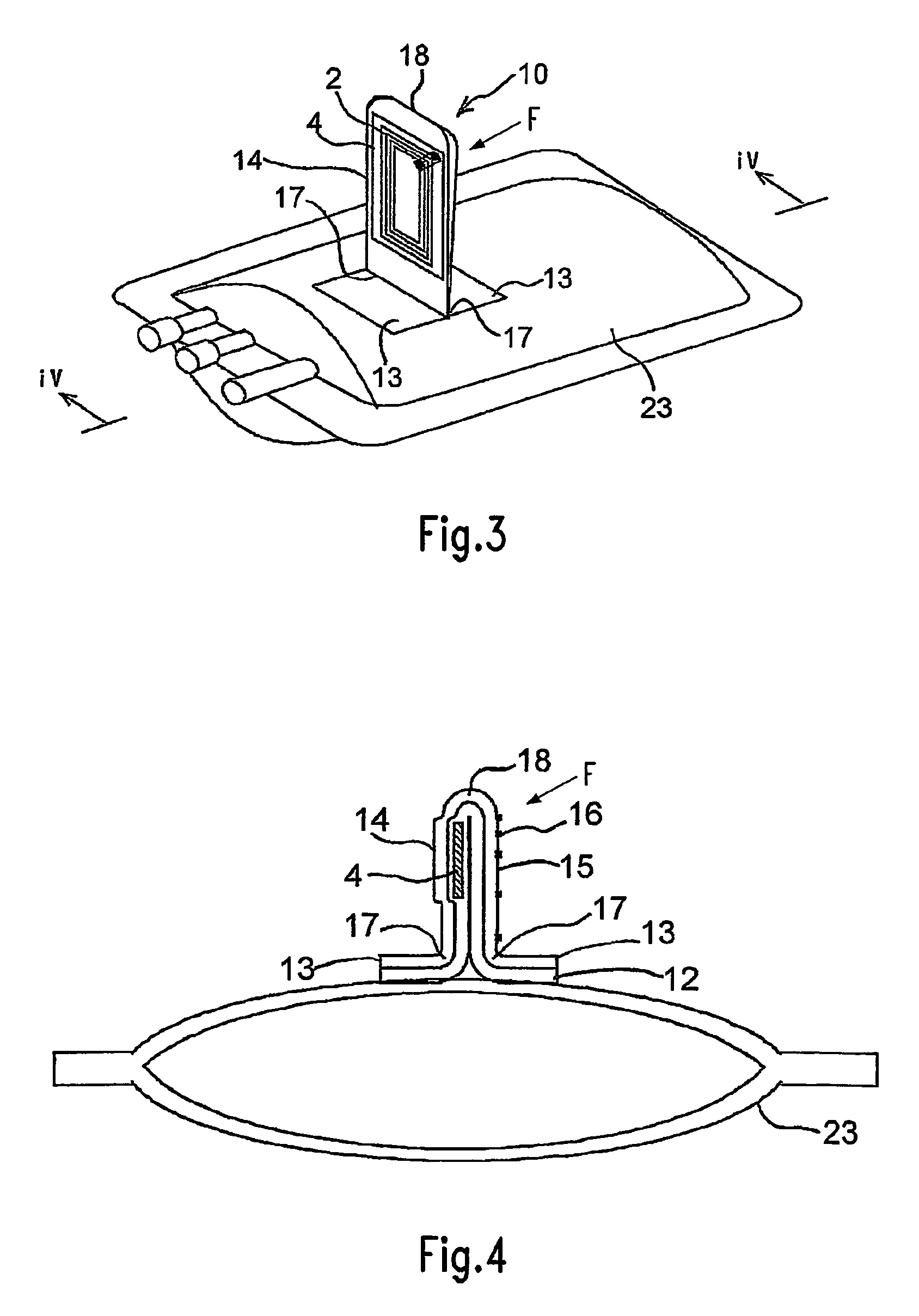
[0097]In FIG. 1, 10 indicates one unit of an RFID label according to an embodiment of the present invention. This RFID label 10 is constructed substantially from a strip-shaped label substrate 11 consisting of a single material or composite material such as a paper, plastic film, synthetic paper, non-woven fabric or the like, an adhesive agent 12 which is applied as a coating to the back surface of this label substrate 11, the abovementioned IC tag 4, and a peeling paper 19 whose surface is coated with a peeling agent such as silicone or the like.

[0098]In the above-mentioned label substrate 11, both ends in the direction of extension constitute pasting parts 13 that are pasted to the object of pasting, and the central part constitutes an IC tag or RFID tag holding part 14 on which the abovementioned IC tag 4 is pasted and held, and an adjacent printing recording part 15. In the example shown in the figures, the back surface of the IC tag 14 is further coated with an adhesive agent 1...


PUM


Abstract

The present invention refers to a label comprising a pasting part for pasting said label to an object and comprising an electronic device preferably for a radio frequency identification (RFID). In order to improve such a label, it is suggested that the electronic device is pivotably connected to said pasting part.

Description

CROSS REFERENCE TO RELATED APPLICATIONS[0001]The present application is a 35 U.S.C. §371 National Phase conversion of PCT / EP2005 / 010497 filed Sep. 28, 2005, which claims priority of European Patent Application No. 04077912.6 filed Oct. 22, 2004 and claims priority of Japanese Patent Application No. 2005-098062 filed Mar. 30, 2005. The PCT International Application was published in the English language.BACKGROUND OF THE INVENTION[0002]The present invention relates to a label comprising at least one pasting part comprising an adhesive agent for pasting the label to an object and comprising a holding part for holding an electronic device, preferably for radio frequency identification (RFID) and to a method for applying such a label to an object, as well as an object with a label and a device for applying the label to an object.[0003]Such labels are commonly known in the art. The electronic device is usually referred to as a RFID tag which comprises an antenna which is connected to an i...

Claims


Application Information

Patent Timeline
Patent Type & Authority Patents(United States)
IPC IPC(8): G06K19/06
CPCG06K19/07749G06K19/0776G09F3/10G09F3/04G06K19/07771G06K19/07G09F3/00B65C7/00
Inventor BARCZYK, VICTOR S.MASANORI, OTSUKASCHWIERS, STEFANTOMOYUKI, KUMABAYASHIHORN, KLAUS
Owner SATO CO LTD
Why Eureka
Eureka Blog
Learn More