
Micro-optical wall shear stress sensor

a micro-optical, wall shear stress technology, applied in the direction of force measurement, force measurement, force measurement, etc., can solve the problems of insufficient state of the art to meet all needs, insufficient indirect measurement techniques, and inability to accurately measure wall shear stress

Inactive Publication Date: 2010-04-20
POLYTECHNIC INSTITUTE OF NEW YORK UNIVERSITY
View PDF4 Cites 13 Cited by
  • Summary
  • Abstract
  • Description
  • Claims
  • Application Information

AI Technical Summary

Benefits of technology

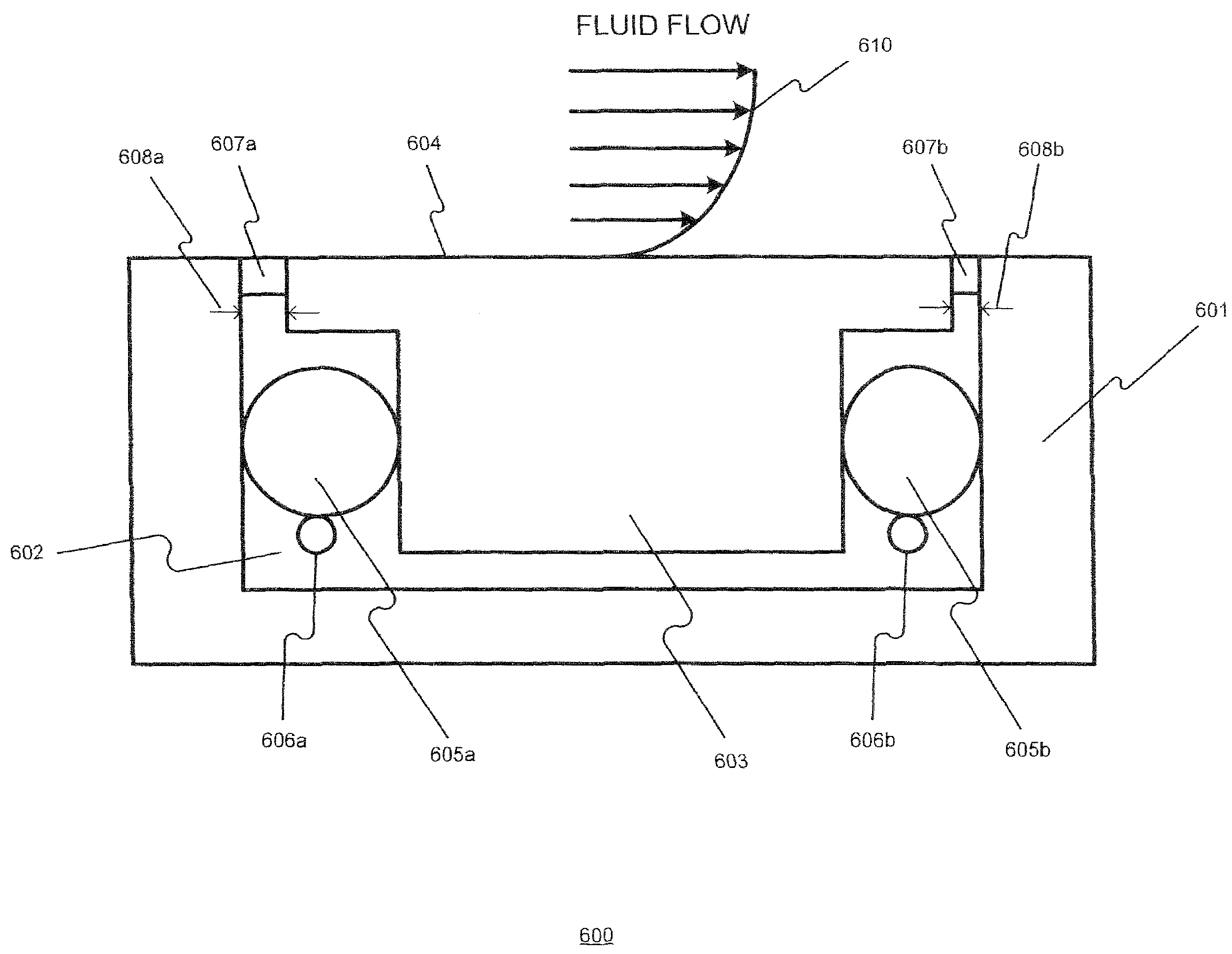
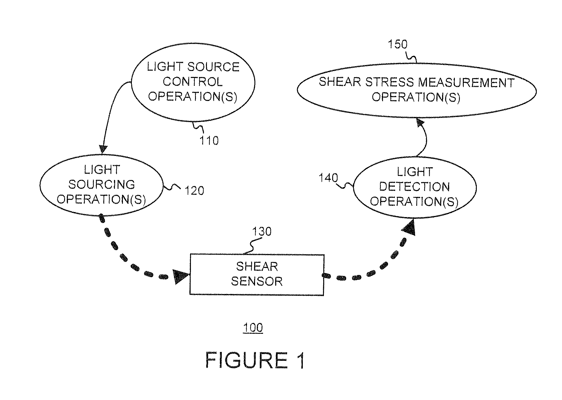
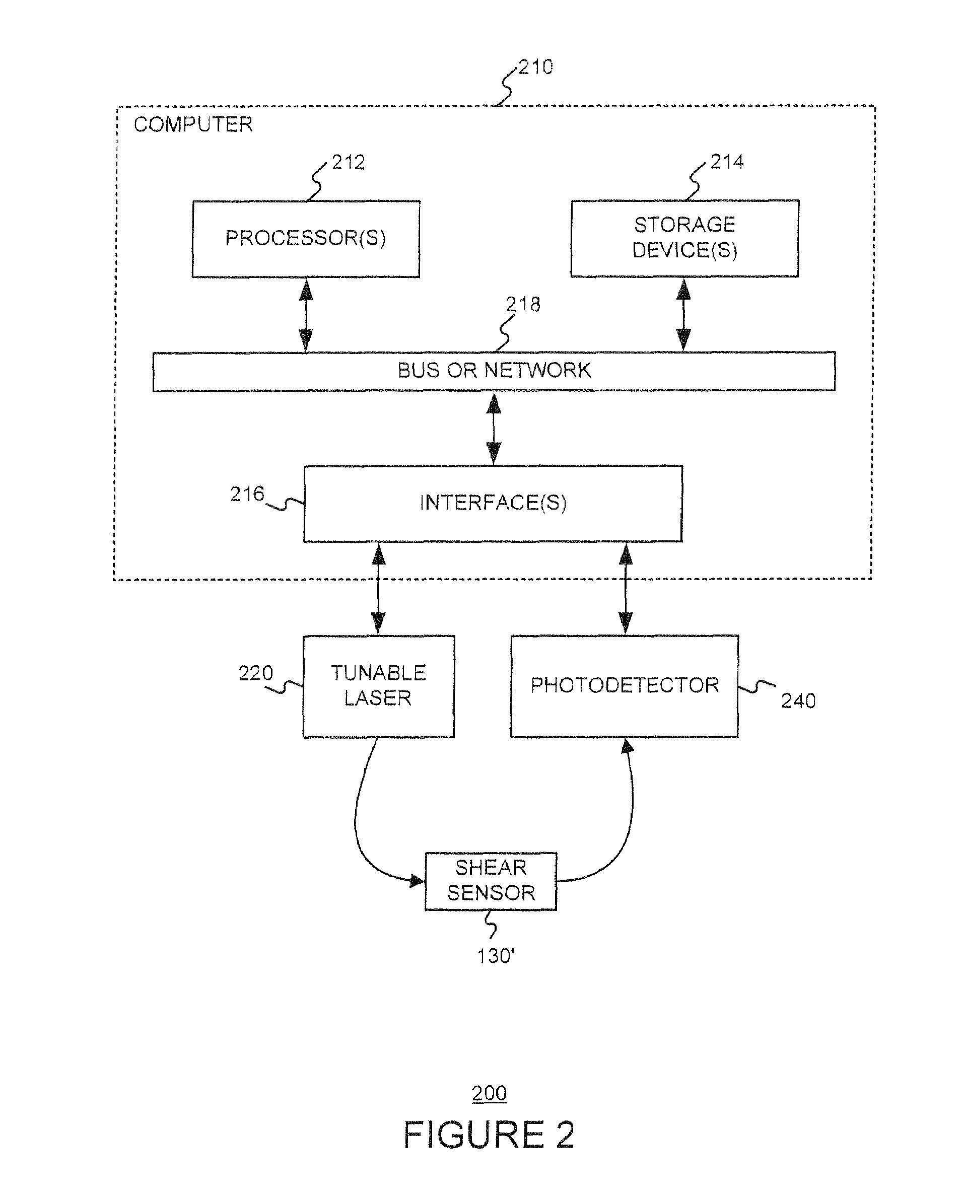
"The present invention provides a sensor for measuring shear stress on a solid surface subject to fluid flow using a micro-resonator. The sensor detects changes in the shape and refractive index of the micro-resonator caused by mechanical stress, which can be related to shear stress. The sensor includes a base component, a sensing component with a sensing surface, a micro-resonator, and an optical carrier optically coupled with the micro-resonator. The sensing component can move with respect to the base component responsive to the fluid flow across the sensing surface. The detection and measurement technique involve coupling light into the optical carrier of the sensor, detecting a property of the light, and determining the shear stress based on the detected property of the light."

Problems solved by technology

The accurate measurement of wall shear stress remains a challenge in fluid mechanics.
Despite the long history of wall shear force measurement attempts using both direct and indirect approaches, the state of the art is still insufficient to meet all needs.
However, such indirect measurement techniques lack the precision required in some applications due to the assumptions, extrapolations, and calculations used to relate the changes in flow properties to the measurement of shear stress.
Unfortunately, this approach does not provide dynamic measurement of the wall shear stress and the spatial resolution can be poor.
This leads to certain drawbacks that include vulnerability to vibration, time response limitations, undesirable flows through gaps, and pressure and temperature gradient effects.
Further, the amount of deflection and / or deformation required for the measurement is too large for some applications.

Method used


Image

  • Micro-optical wall shear stress sensor
  • Micro-optical wall shear stress sensor
  • Micro-optical wall shear stress sensor

Examples


Embodiment Construction

[0024]The following detailed description is presented to enable one skilled in the art to make and use the invention, and is provided in the context of particular embodiments and methods. Various modifications to the disclosed embodiments and methods will be apparent to those skilled in the art, and the general principles set forth below may be applied to other embodiments, methods and applications. Thus, the present invention is not intended to be limited to the embodiments and methods shown and the inventors regard their invention as the following disclosed methods, apparatus and materials and any other patentable subject matter to the extent that they are patentable.

[0025]No element, act or instruction used in the description should be construed as critical or essential to the invention unless explicitly described as such. Also, as used herein, the article “a” is intended to include one or more items. Where only one item is intended, the term “one” or similar language is used.

[00...


PUM


Abstract

Stresses and strains on a solid surface subject to a fluid flow are dynamically measured based on a shift of optical resonances of a micro-resonator. The elastic deformation and refractive index change of a micro-resonator due to mechanical stress is exploited. With this approach, mechanical deformations in the order of a nanometer can be detected and related to shear stress.

Description

§0. RELATED APPLICATIONS[0001]Benefit is claimed, under 35 U.S.C. §119(e) (1), to the filing date of U.S. provisional patent application Ser. No. 60 / 877,391 (referred to as “the '391 provisional”), titled “MICRO-OPTICAL WALL SHEAR STRESS SENSOR”, filed on Dec. 27, 2006, and listing Volkan Otugen and Valery Sheverev as the inventors, for any inventions disclosed in the manner provided by 35 U.S.C. §112, 1. The '391 provisional application is expressly incorporated herein by reference. The scope of the present invention is not limited to any requirements of the specific embodiments described in the '391 provisional application.§1. BACKGROUND OF THE INVENTION[0002]§1.1 Field of the Invention[0003]The present invention concerns the measurement of wall shear stress (or skin friction) in a fluid flow. More specifically, the present invention concerns an optical micro-sensor which can measure wall shear stress (or skin friction) due to a flowing fluid over a solid surface with very high s...

Claims


Application Information

Patent Timeline
Patent Type & Authority Patents(United States)
IPC IPC(8): G01B9/02
CPCG01L1/243
Inventor OTUGEN, VOLKANSHEVEREV, VALERY
Owner POLYTECHNIC INSTITUTE OF NEW YORK UNIVERSITY
Learn More