
Pre-filled syringe

a syringe and pre-filled technology, applied in the field of pre-filled syringes, can solve the problems of air invading the medicine, air bubbles, and a lot of time and effort, and achieve the effect of preventing uneven dissolution of the medicine, easy manufacturing, and structure of the nozzle member

Active Publication Date: 2010-04-20
NIPRO CORP
View PDF17 Cites 22 Cited by
  • Summary
  • Abstract
  • Description
  • Claims
  • Application Information

AI Technical Summary

Benefits of technology

The present invention provides a pre-filled syringe that makes it easy to expel air bubbles in the liquid medicine and prevent uneven dissolution of the medicine during shaking. The syringe has a nozzle part with a front end gasket and liquid flow passages that allow air bubbles to be easily expelled. The front end gasket and intermediate gasket in the barrel fluid-tightly partition the inside of the barrel, and a bypass allows the liquid medicine to flow between the front and rear chambers. The sectional area of the liquid flow passages gradually decreases from the base end to the front end, and a concave part or concaves can be formed in the front end gasket to facilitate the expulsion of air bubbles. The structure of the nozzle member is simple and easy to manufacture.

Problems solved by technology

However, this method is intricate in its operation, so that a lot of time and effort is required, and in addition, there is a fear that bacteria in the air will invade the medicine, and a high possibility that foreign objects like such as particles of glass in the ampule, particles of rubber in the vial, and the like are mixed in the medicine (i.e., coring).
However, since a rear face of the front end stopper and a front face of the base end stopper are smooth faces perpendicular to an axis of the tubular body, there has existed a problem that, after the front end stopper enters the front end stopper accommodation part, even if the liquid medicine is pushed by additionally moving forward the base end stopper, air bubbles in the tubular body are left in the rear face of the front end stopper and are difficult to expel to the outside.
Further, since the front end and base end stoppers are made of a rubber, the air bubbles are liable to adhere to a peripheral face in comparison with glass, a plastic or the like, which forms the tubular body, and, also from this point, there has been a problem that the air bubbles are difficult to expel from the injection needle attached to the needle holder.
Since almost all of the front chamber is filled with air and it is necessary to violently shake the device to dissolve the medicine in some cases, air bubbles adhere to a rear face of the seal stopper and discharge of the air bubbles to the outside is difficult.
However, there are problems that since notch provided in the peripheral end edge of the rear face of the seal stopper extends to a side face, airtightness of a seal part is reduced, and that even if the seal stopper is moved forward during preparation for dissolution, since a liquid flow is made through the notch just before the seal stopper is completely accommodated in a seal stopper accommodation part existing in an inside in a base end side of the needle holder, some gap occurs in a forward portion of the seal stopper existing in an inside of the needle holder, so that when the plunger rod is pushed to the end on administering an injection to a patient it does not move smoothly, thereby generating an uncomfortable feeling.
Further, there is also a problem that if the medicine and the solution are shaken in order to be dissolved, medicine, which is insufficiently dissolved, enters through the notch into a concave between seals existing in an outer periphery of the seal stopper and clogs the concave, and generally the notch is made small in order to reduce a residual liquid as much as possible, so that the residual liquid is difficult to return to the front chamber.
Additionally, there has been a problem that in a case where a distance between the mutual notches is large like a case where an inner capacity of the pre-filled syringe is large and thus its, inner diameter becomes large, unless an operator operates such that a position of the notch is positioned upward, the air bubbles adhere to the rear face of the seal stopper and remain intact, so that there is a tear that the air bubbles are not discharged to the outside and there are changes per one operation.

Method used


Image

  • Pre-filled syringe
  • Pre-filled syringe
  • Pre-filled syringe

Examples


second embodiment

FIG. 5 is a cross-sectional view showing a one-chamber type pre-filled syringe that is the present invention.

embodiment 1

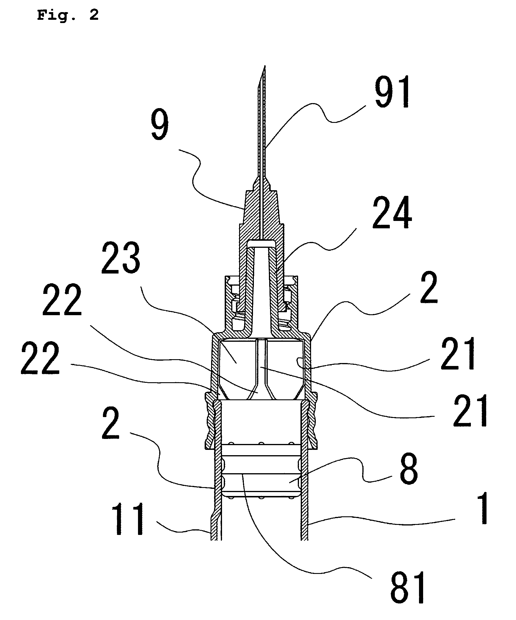
[0024]A pre-filled syringe A that is one implementation mode of the present invention has, among the above characteristics, (1), (2), (3) and (5), and additionally it is desirable to have characteristic (4). Concretely, as shown in FIG. 1-FIG. 4, the pre-filled syringe A is a two-chamber type pre-filled syringe possessing a barrel 1 whose front end and base end are open, an intermediate gasket 6 fluid-tightly partitioning an inside of the barrel 1 into a front chamber and a rear chamber, a base end gasket 4 in a base end side relative to the intermediate gasket 6 and sealing the inside of the barrel 1, a plunger rod 12 connected to a base end of the base end gasket 4, a front end gasket 8 placed in a front end side relative to the intermediate gasket 6 and sealing the inside of the barrel 1, a nozzle member 2 which is fluid-tightly engaged with a front end of the barrel 1 and to which an injection needle 9 is detachably attached, and a flange part 3 provided in a base end part of th...


PUM


Abstract

A pre-filled syringe including a barrel 1, a base end gasket 4 which is fluid-tightly slidable in the barrel 1, a front end gasket 8 which is fluid-tightly slidable in the barrel 1, and a nozzle part 2 provided in a front end of the barrel 1, wherein the nozzle part 2 includes a front end gasket accommodation part 23 which is capable of accommodating the front end gasket 8, and liquid flow passages 21 extending in an axial direction in an inner periphery wall, through which a liquid medicine can pass when the front end gasket 23 is accommodated in the front end gasket accommodation part 23, and a sectional area of a front end of the liquid flow passages 21 is smaller than a sectional area of a base end.

Description

TECHNICAL FIELD[0001]The present invention relates to a pre-filled syringe. More specifically, it relates to a pre-filled syringe in which an inside of a barrel is partitioned by a gasket, a liquid medicine or a solution and a powder medicine are stored, and which includes a nozzle part to which an injection needle is detachably attached.RELATED ART[0002]A conventional preparation of liquid medicine is such that ampules, vials, or the like in which medicines are separately stored until just before use, are opened by using a throwaway syringe or injection needle, or the like and medicines are prepared at the time of use, and then the prepared medicine is used. However, this method is intricate in its operation, so that a lot of time and effort is required, and in addition, there is a fear that bacteria in the air will invade the medicine, and a high possibility that foreign objects like such as particles of glass in the ampule, particles of rubber in the vial, and the like are mixed ...

Claims


Application Information

Patent Timeline
Patent Type & Authority Patents(United States)
IPC IPC(8): A61M5/00
CPCA61M5/3134A61M5/31596A61M2005/3139A61M5/347A61M2005/3132A61M5/3202
Inventor HASEGAWA, MITSURU
Owner NIPRO CORP
Learn More