Oil pump structure of transmission
a technology of oil pump and transmission shaft, which is applied in the direction of piston pump, positive displacement liquid engine, gearing, etc., can solve the problems of increasing fuel consumption rate, affecting the flow rate, and increasing so as to reduce the axial dimension of the outer peripheral portion
- Summary
- Abstract
- Description
- Claims
- Application Information
AI Technical Summary
Benefits of technology
Problems solved by technology
Method used
Image
Examples
Embodiment Construction
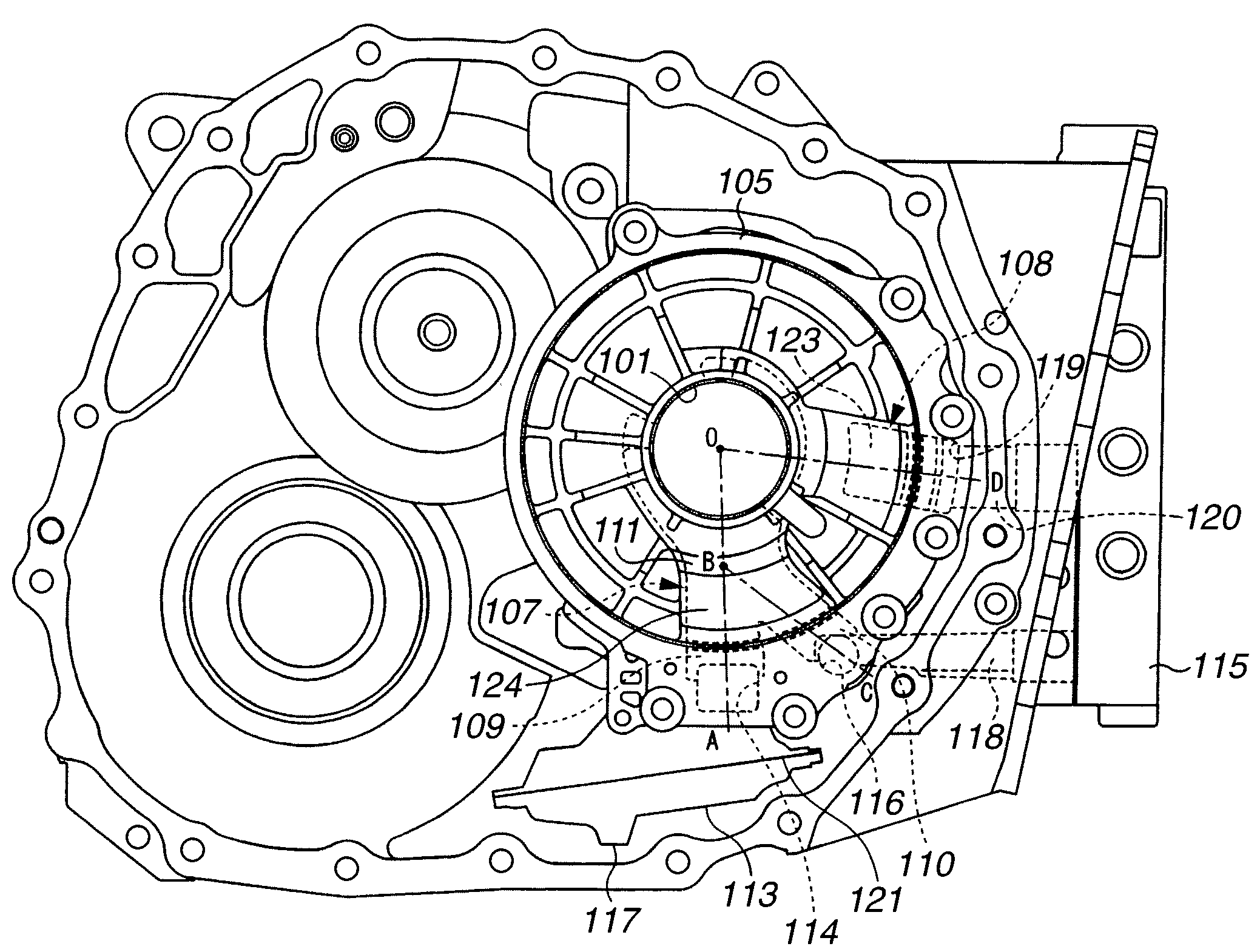
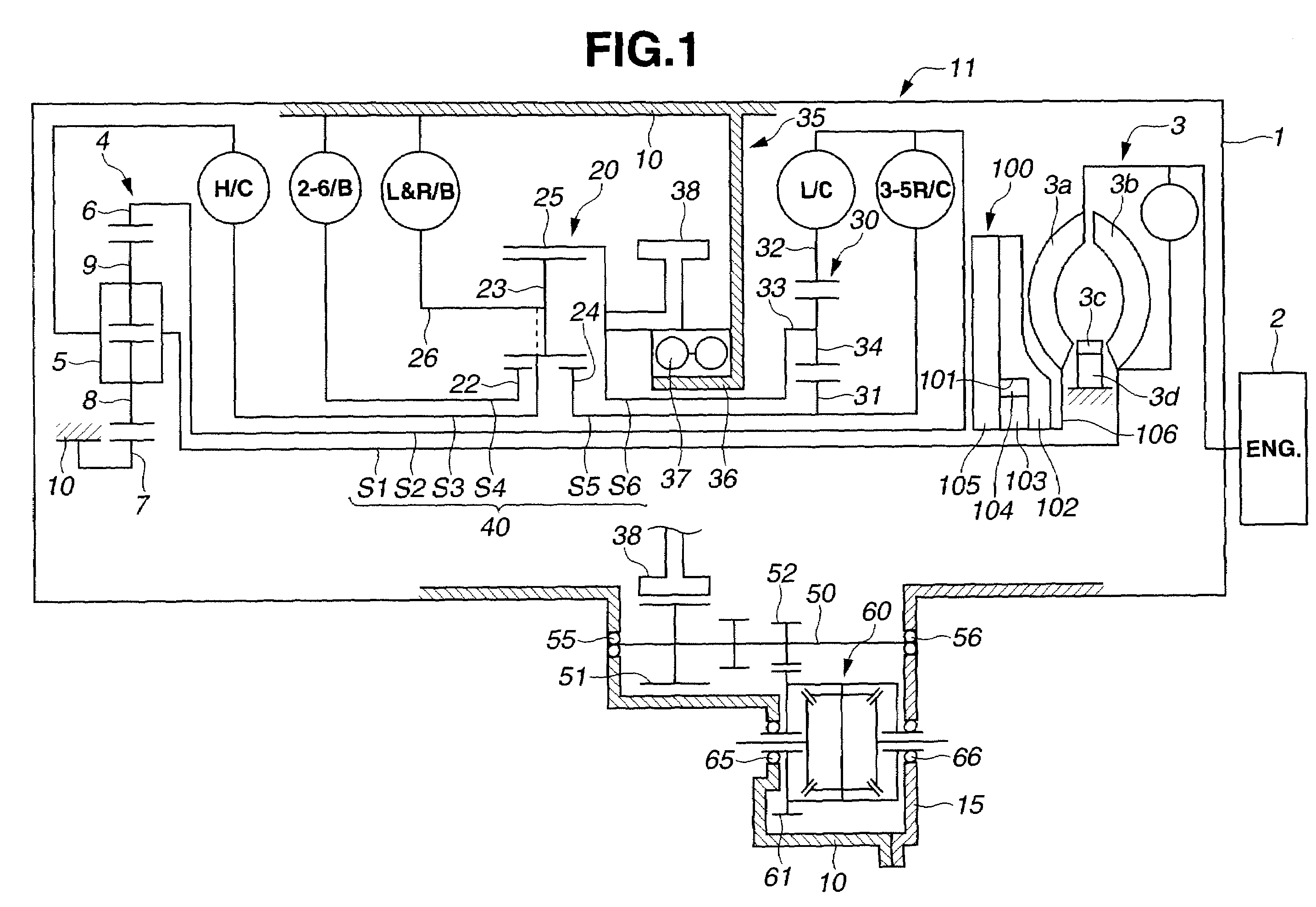
[0022]Referring now to the drawings, particularly to FIG. 1, the oil pump structure of the embodiment is exemplified in an automotive automatic transmission 1, which is comprised of three basic parts, namely a torque converter 3, and planetary-gear systems (described later) included in a transmission mechanism 11. Automatic transmission 1 is connected to an engine 2 and mounted on an automotive vehicle (not shown). Torque converter 3 passes the engine power to the planetary-gear systems.
[0023]Torque converter 3 is comprised of a pump impeller 3a, a turbine runner 3b, a one-way clutch 3d, and a stator 3c. During operation of engine 2, the engine power is transmitted to pump impeller 3a. Turbine runner 3b is located to be opposed to pump impeller 3a for power transmission to a first shaft S1. Stator 3c is located between pump impeller 3a (the driving member) and turbine runner 3b (the driven member). Stator 3c is mounted on one-way clutch 3d, which permits stator 3c to run free when t...
PUM
 Abstract
Description
Claims
Application Information
 - R&D
- Intellectual Property
- Life Sciences
- Materials
- Tech Scout
- Unparalleled Data Quality
- Higher Quality Content
- 60% Fewer Hallucinations
Browse by: Latest US Patents, China's latest patents, Technical Efficacy Thesaurus, Application Domain, Technology Topic, Popular Technical Reports.
© 2025 PatSnap. All rights reserved.Legal|Privacy policy|Modern Slavery Act Transparency Statement|Sitemap|About US| Contact US: help@patsnap.com


