
Range image generating apparatus

a technology of generating apparatus and range image, which is applied in the direction of distance measurement, surveying and navigation, instruments, etc., to achieve the effect of preventing or reducing the generation of range images

Active Publication Date: 2010-04-13
STANLEY ELECTRIC CO LTD
View PDF14 Cites 23 Cited by
  • Summary
  • Abstract
  • Description
  • Claims
  • Application Information

AI Technical Summary

Benefits of technology

The present invention provides a range image generating apparatus that can prevent or reduce interference between range images, even if they have erroneous distance values. The apparatus includes a light source that radiates modulated light to a target space, an image pickup element that converts the reflected light into charges, and a distribution unit that distributes the charges to multiple charge storage units in synchronization with the modulation frequency of the light source. The apparatus also includes a frequency changing unit that changes the modulation frequency for each frame rate or charge storage time, resulting in a small probability of interference between range images generated by different apparatuses. Additionally, the apparatus can determine the pixel indicating a value for the light source of another range image generating apparatus and replace its distance value with the distance value of a nearby pixel to obtain a proper range image even if the modulation frequencies of the two apparatuses are the same.

Problems solved by technology

At that time, if the modulation frequency of the modulated light radiated from the own range image generating apparatus and the modulation frequency of the modulated light radiated from the other range image generating apparatus are the same, the own range image generating apparatus may erroneously detect a phase difference of an incident light containing the modulated light radiated from the light source of the other range image generating apparatus and a reflected light components of the modulated light radiated from the light source of the other range image generating apparatus, resulting in generation of a range image including pixels with erroneous distance values (hereinafter, also referred to as a “range image with interference”).

Method used


Image

  • Range image generating apparatus
  • Range image generating apparatus
  • Range image generating apparatus

Examples


Embodiment Construction

[0036]Hereinafter, a range image generating apparatus according to an embodiment of the present invention will be described with reference to the drawings.

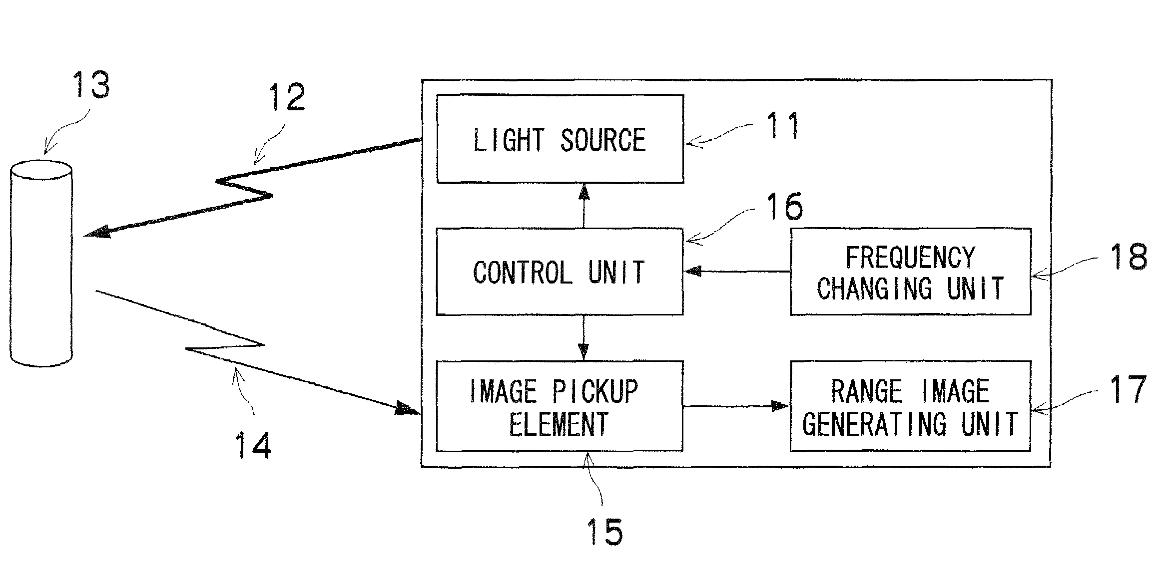
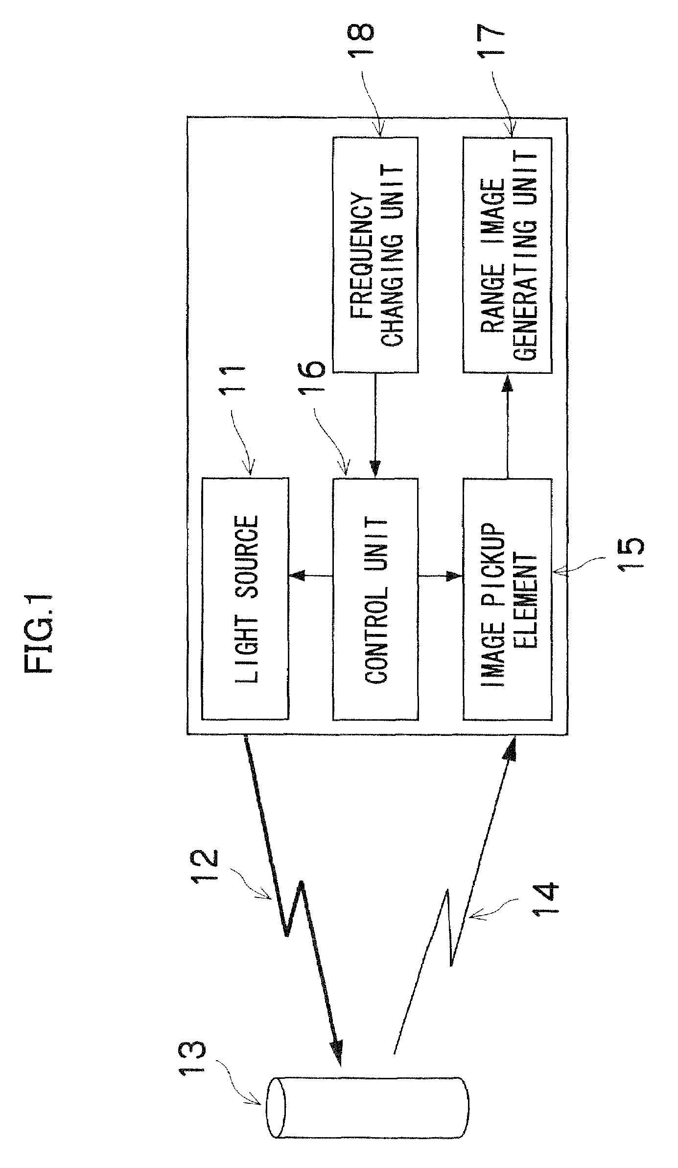
[0037]FIG. 1 is a block diagram of a range image generating apparatus according to a first embodiment. As shown in FIG. 1, a range image generating apparatus 1, which is to be mounted in a vehicle such as an automobile, includes a time of light flight-type range image sensor 10 (hereinafter, referred to as the “range image sensor 10”). The range image sensor 10 includes, e.g., a light source 11, an image pickup element 15, a control unit 16, a range image generating unit 17, a frequency changing unit 18.

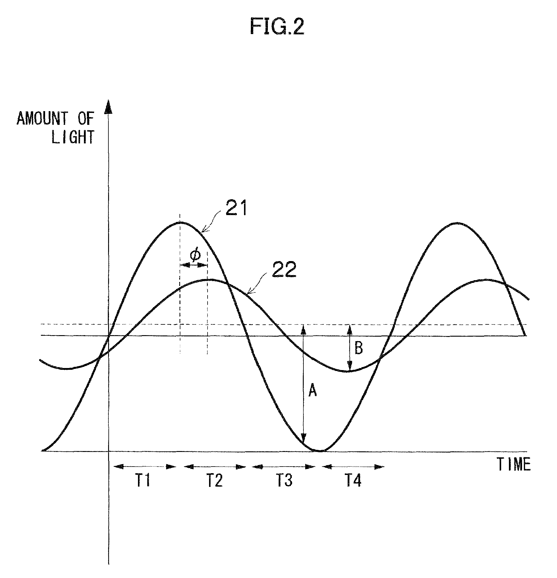
[0038]The light source 11 is a light source that radiates modulated light to a target space (for example, infrared light or visible light rapidly modulated by means of sine wave or rectangular wave, etc.), and a device that can perform high-speed modulation, such as an LED, is used for the light source 11. The image pickup element ...


PUM


Abstract

A range image generating apparatus capable of preventing or reducing generation of range images with interference, which contain e.g., pixels with erroneous distance values is provided. The range image generating apparatus includes: a light source radiating a light; an image pickup element; a range image generating unit; a frequency changing unit that changes a modulation frequency for each frame rate or charge storage time; and a control unit that controls the light source and the image pickup element in synchronization with the modulation frequency changed by the frequency changing unit.

Description

BACKGROUND OF THE INVENTION[0001]1. Field of the Invention[0002]The present invention relates to a range image generating apparatus, and specifically relates to a range image generating apparatus capable of preventing or reducing generation of range images with interference, which include, e.g., pixels with erroneous distance values.[0003]2. Description of the Related Art[0004]Conventionally, there has been known a range image generating apparatus that generates a range image whose pixel values are distance values, by radiating modulated light from a light source, receiving light reflected by an object and converting the light into charges by means of photoelectric conversion elements, distributing the charges converted by the photoelectric conversion elements into a plurality of charge storage units in synchronization with modulation of the light source, and performing a predetermined calculation based on the charges stored in the plurality of charge storage units (for example, see...

Claims


Application Information

Patent Timeline
Patent Type & Authority Patents(United States)
IPC IPC(8): G01C3/08G06K9/20H04N23/75
CPCG01S7/493G01S17/36G01S7/4808G01S17/936G01S17/89G01S17/931G01S17/894
Inventor IKENO, RYOHEIKAWATA, TADASHIURABE, HIDEKI
Owner STANLEY ELECTRIC CO LTD
Learn More