
Apparatus for monitoring engine exhaust

a technology for engine exhaust and apparatus, which is applied in the direction of instruments, structural/machine measurement, withdrawal sample devices, etc., to achieve the effects of reducing the likelihood of spurious measurements, increasing the sensitivity of the apparatus, and absorbing the body easily

Active Publication Date: 2010-04-13
HARTRIDGE L
View PDF11 Cites 83 Cited by
  • Summary
  • Abstract
  • Description
  • Claims
  • Application Information

AI Technical Summary

Benefits of technology

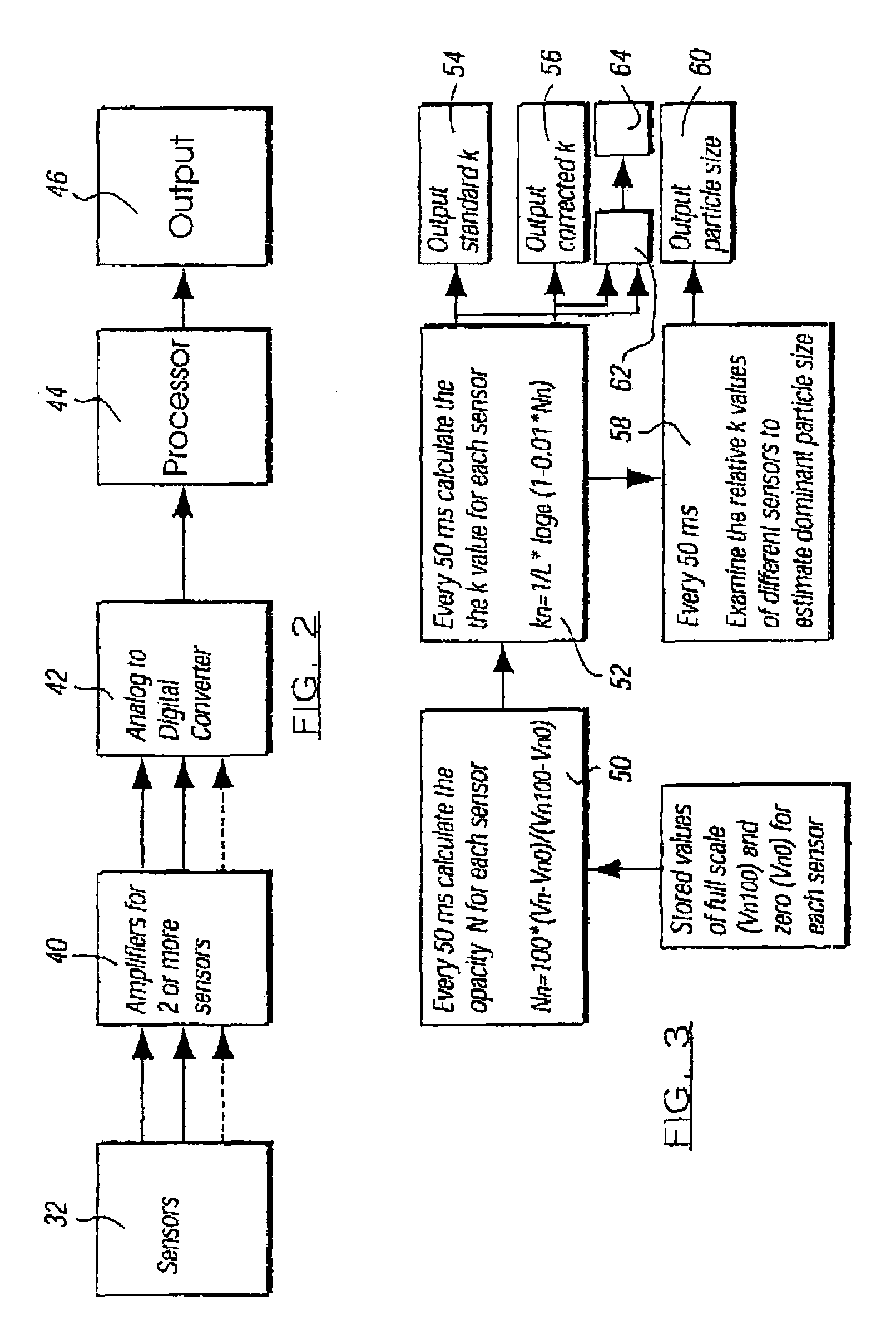
"The present invention is about an apparatus and method for monitoring engine exhaust. The apparatus uses electromagnetic radiation to monitor the exhaust and measures the attenuation of this radiation caused by the presence of nitrogen dioxide in the exhaust. The apparatus has detectors that can measure the attenuation of the radiation at different wavelengths, which are chosen to have the same attenuation caused by nitrogen dioxide. This allows the apparatus to provide a clear assessment of the size of particles in the exhaust. The detectors are preferably able to provide different measures of the radiation for more than two different wavelengths. The apparatus also includes blowers to prevent the detectors from being permanently marked by materials in the exhaust. The light source used in the apparatus emits electromagnetic energy across a range of wavelengths that includes the different wavelengths used for monitoring. The apparatus calculates a k value for each detector using an equation based on the optical path length and the opacity of the exhaust. The method involves directing electromagnetic radiation through the exhaust in a chamber and measuring the attenuation of the radiation for at least two different wavelengths. The technical effects of the invention include improved accuracy in measuring the size of particles in the exhaust and better monitoring of engine exhaust emissions."

Problems solved by technology

This in turn is significant from the point of view of harmful pollution because particles of a small size are more readily absorbed by the body, especially lung tissue, than particles of a larger size.

Method used


Image

  • Apparatus for monitoring engine exhaust
  • Apparatus for monitoring engine exhaust
  • Apparatus for monitoring engine exhaust

Examples


Embodiment Construction

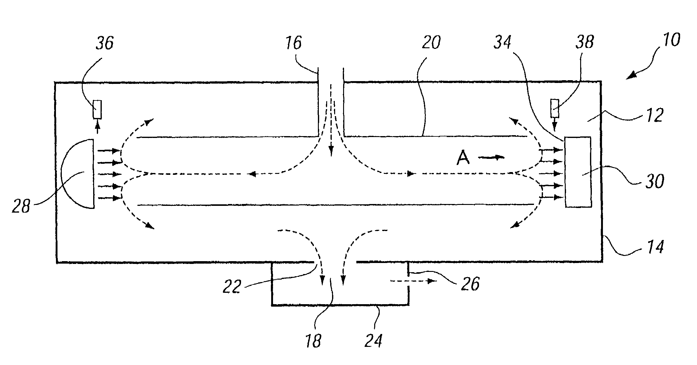
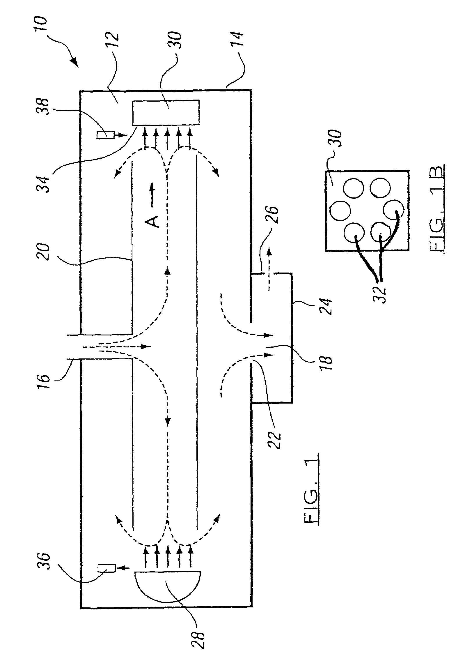
[0022]The apparatus 10 shown in FIG. 1 comprises an enclosure 12 defined by a generally cylindrical closed housing 14, having an inlet 16 positioned halfway along the housing 14, and which is adapted to be connected to an engine exhaust, and an outlet 18, which is also positioned halfway along the length of the housing 14, but which is diametrically opposite the inlet 16. The outlet 18 is for the extraction of waste exhaust / airmix from the enclosure 12. The inlet 16 is connected to feed exhaust through a wall of a cylinder 20, which defines a measuring chamber, at a position equidistant from the ends thereof. The cylinder 20 is open at both ends. As a result a path is provided for exhaust which starts at the inlet 16, progresses in both directions therethrough outwardly towards the respective ends of the cylinder 20 close to the closed ends of the housing 14, back along the enclosure 12 towards a position halfway along the housing 14 around the outside of the cylinder 20 and thence ...


PUM

PropertyMeasurementUnit
wavelengthsaaaaaaaaaa
wavelengthaaaaaaaaaa

Abstract

An apparatus for monitoring the exhaust of an engine includes a flow-through chamber for receiving exhaust, a source of electromagnetic radiation and a detector. The source provides electromagnetic radiation in a range comprising the infrared, visible and ultraviolet wavelengths. The source and a detector are arranged so that radiation passing through the chamber is incident on the detector. An electronic circuit is connected to the detector to provide a signal indicative of the attenuation of the radiation by particles in the exhaust in the chamber. The detector provides respective measures of radiation which it receives for at least two different wavelengths of the radiation, and the electronic circuit provides corresponding electrical signals indicating the attenuation of the two different wavelengths by particles within the exhaust in the chamber. The wavelengths are selected to be those for which the attenuation caused by nitrogen dioxide in the exhaust is substantially the same.

Description

TECHNICAL FIELD[0001]This invention relates to the an of apparatus for monitoring the exhaust of internal combustion engines.BACKGROUND OF THE INVENTION[0002]The present invention is directed to apparatus for monitoring engine exhaust, comprising a chamber for receiving such exhaust, an inlet of the chamber adapted to be connected to the engine exhaust and an outlet from the chamber to enable exhaust to escape therefrom, so that exhaust from the engine can flow through the chamber continuously, a source of electromagnetic radiation which is of a wavelength within a range comprising the infrared, visible and ultraviolet wavelengths, detector means which detects the amount of such radiation it receives, the source and the detector being so arranged that radiation emitted by the source is received by the detector after the radiation has passed through the chamber, and electrical means connected to the detector to provide an electrical signal which is indicative of the attenuation of th...

Claims


Application Information

Patent Timeline
Patent Type & Authority Patents(United States)
IPC IPC(8): G01N15/06G01J5/02G01N21/00G01M15/10G01N1/22G01N15/02G01N21/35G01N21/53
CPCG01M15/108G01N1/2252G01N21/534G01N15/0205G01N2021/3545G01N15/0656
Inventor JONES, MICHAEL LLOYD
Owner HARTRIDGE L
Learn More