
Secondary feeder rotor behind undershot precutter

a feeder rotor and precutter technology, applied in the field of agricultural harvesters, can solve the problems of inordinately long and difficult to handle cylindrical rolls, affecting the quality of bales, so as to reduce the width

Active Publication Date: 2010-04-13
DEERE & CO
View PDF26 Cites 36 Cited by
  • Summary
  • Abstract
  • Description
  • Claims
  • Application Information

AI Technical Summary

Benefits of technology

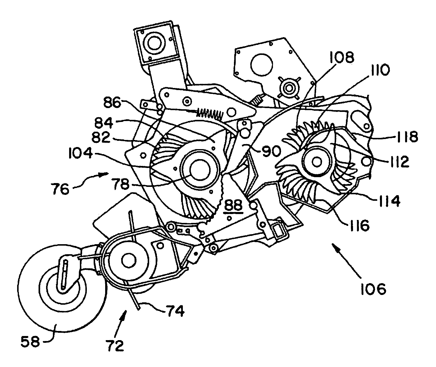
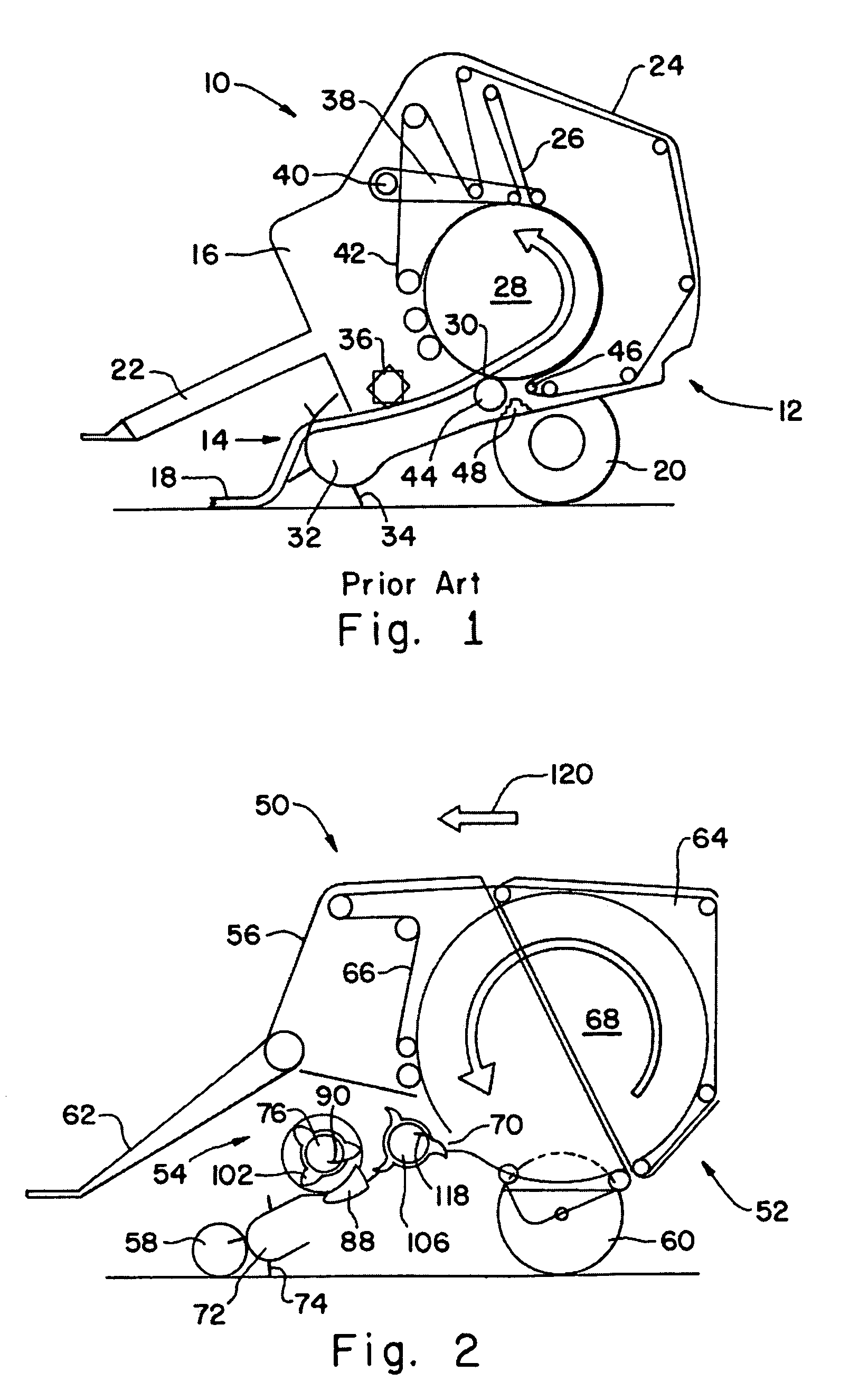
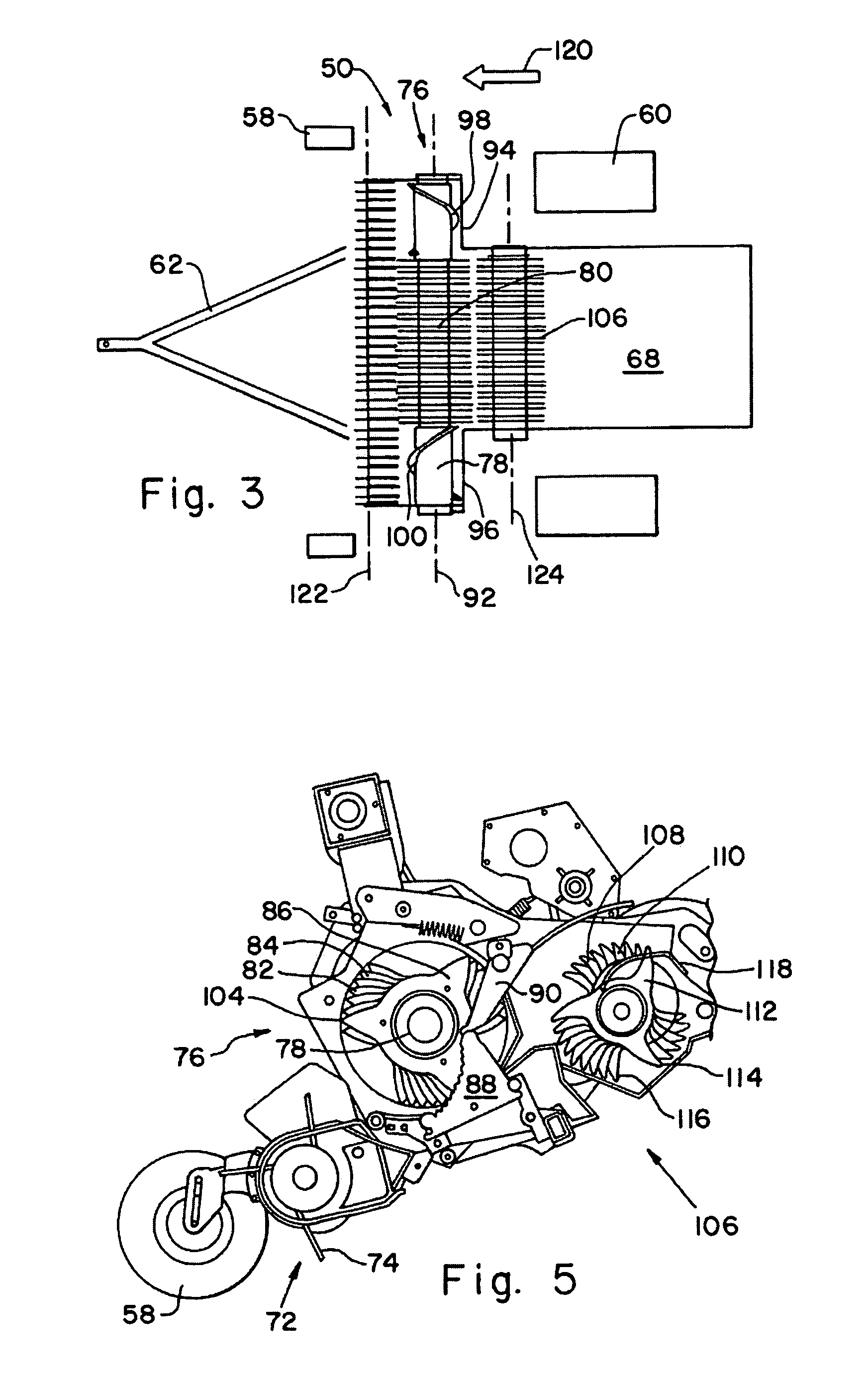
The invention is a crop delivery arrangement for picking up and transporting crop to a baling chamber. It includes a crop take-up device, a crop processing arrangement with an undershot precutter rotor, and an overshot secondary feed rotor. The crop take-up device is wider than the crop processing arrangement and the inlet. The invention also includes a transverse conveyor for receiving crop from the take-up device and delivering it to the precutter rotor. The invention also describes a combination crop cutting and conveying assembly for use in an agricultural harvesting machine. The assembly includes a cylindrical rotor shaft supporting crop conveying members, cutting blades, and strippers. The overshot feed rotor receives cut crop from the strippers and conveys it to the baling chamber inlet. The technical effects of the invention include improved crop processing and more efficient crop delivery to the baling chamber.

Problems solved by technology

A pick-up or take-up device with a wide swath is desirable to minimize the number of harvester passes necessary to clear a field, however, directly feeding the crop from such a wide swath to a baling chamber would result in an inordinately long and difficult to handle cylindrical roll.
In these balers, condensed and compressed crop to be baled can bring about jams in the cutter head.
Since the floor roller is not a positive feeder of crop, poor bale starting remains a problem.
Significant crop loss often occurs behind the floor roller in front of the belts of the lower gate roller.

Method used


Image

  • Secondary feeder rotor behind undershot precutter
  • Secondary feeder rotor behind undershot precutter
  • Secondary feeder rotor behind undershot precutter

Examples


Embodiment Construction

[0014]Referring now to FIG. 1, there is shown a baler 10 of known design having a chassis 12 and a crop supply assembly 14. The baler 10 is configured as a large round baler. The baler 10 is applied on the field and takes up crop 18 deposited on the ground in wide swaths, in order to subject it to a baling process. In the case of a large round baler, a configuration with a baling chamber of fixed size as well as a chamber of variable size can be considered. The chassis 12 includes a frame 16 supported on wheels 20, a towbar 22, side walls 24 and a baling arrangement 26. An axle forms the connection between the wheels 20 and the frame 16 and can be attached or configured as spring-supported or rigidly. The wheels support the frame 16 on the ground so that it can move freely and be drawn across the field by the tow bar 22 due to its connection with a towing vehicle. The side walls 24 are spaced away from each other by the width of, and define opposite sides of, the baling chamber 28. ...


PUM


Abstract

A round baler has an overshot secondary rotor located behind an undershot precutter rotor. The round baler has a relatively wide swath crop pick-up and a baling chamber with a significantly more narrow inlet. The precutter rotor has a central region supporting a plurality of rotatable crop conveying members interleaved by both a set of relatively fixed cutting blades and a set of relatively fixed strippers for urging cut crop away from the rotor, and end regions supporting rotatable helically disposed bands for receiving wide swath crop from the pick-up arrangement and urging the received crop toward the central region. The secondary rotor creates an S-shaped or serpentine crop path with minimal dead space and is a positive feeder for bale starting. Stationary strippers for the secondary rotor prevent crop from exiting the baler behind the secondary rotor.

Description

FIELD OF THE INVENTION[0001]The present invention relates to agricultural harvesters and more particularly to a crop pick-up and baling machine.BACKGROUND OF THE INVENTION[0002]Large generally cylindrical rolls of hay or similar crop material are familiar late summer sights in farm fields. Such bales are typically formed by a tractor drawn harvesting machine including near its leading edge a pick-up device in the form of a rotor having a plurality of outwardly extending tines. Rotor rotation serves to pick the crop upwardly over the rotor and rearwardly (opposite the longitudinal direction of harvester travel) for further processing. A comb-like array of fixed elements strip the crop from the tines at an appropriate location to prevent the crop from being returned to the ground. A pick-up or take-up device with a wide swath is desirable to minimize the number of harvester passes necessary to clear a field, however, directly feeding the crop from such a wide swath to a baling chamber...

Claims


Application Information

Patent Timeline
Patent Type & Authority Patents(United States)
IPC IPC(8): A01D39/00A01D43/02A01D75/00
CPCA01D90/04A01F15/106A01F2015/108Y02A40/28
Inventor VIAUD, JEANANSTEY, HENRY D.DERSCHEID, DANIEL E.
Owner DEERE & CO
Learn More