Techniques to deterministically reduce signal interference

a technology of signal interference and deterministically reducing techniques, applied in the direction of electrical equipment, radio transmission, transmission, etc., can solve the problem that the receiver is unable to accurately reproduce the transmitted data signal

Active Publication Date: 2010-04-06
APPLE INC
View PDF26 Cites 3 Cited by
  • Summary
  • Abstract
  • Description
  • Claims
  • Application Information

AI Technical Summary

Problems solved by technology

The undesired signals may cause interference such that the receiver is unable to accurately reproduce the transmitted data signal.

Method used


Image

  • Techniques to deterministically reduce signal interference
  • Techniques to deterministically reduce signal interference
  • Techniques to deterministically reduce signal interference

Examples


Embodiment Construction

[0011]Reference throughout this specification to “one embodiment” or “an embodiment” means that a particular feature, structure, or characteristic described in connection with the embodiment is included in at least one embodiment of the present invention. Thus, the appearances of the phrase “in one embodiment” or “an embodiment” in various places throughout this specification are not necessarily all referring to the same embodiment. Furthermore, the particular features, structures, or characteristics may be combined in one or more embodiments.

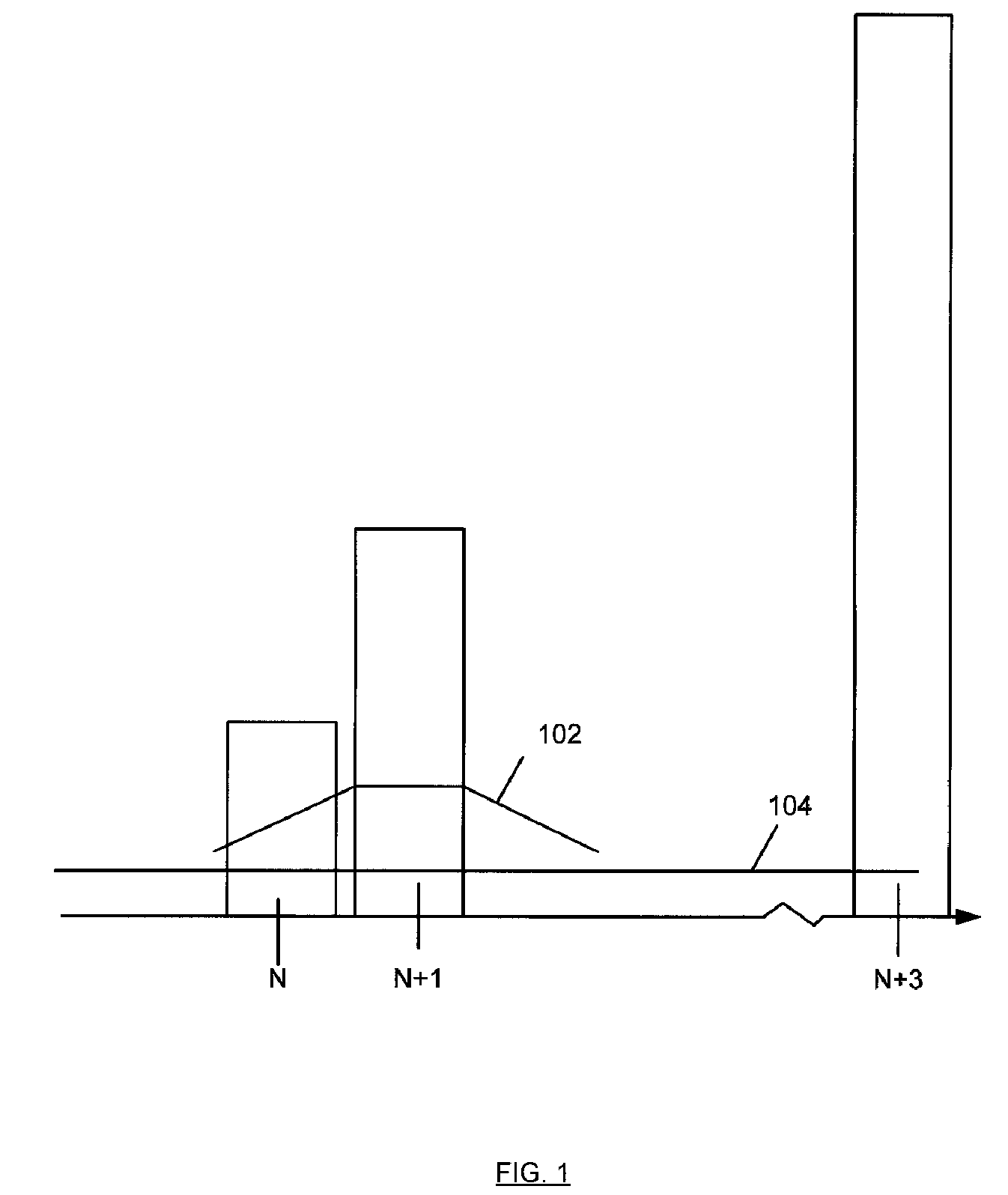
[0012]FIG. 1 depicts an example of interference arising from interfering signals. A signal at frequency N may be a desired digital signal. For example, the desired signal may carry video or other information and may be transmitted wirelessly. Signals from adjacent frequencies of N+1 and N+3 are shown. For example, N+1 may be 6 MHz from frequency N whereas N+3 may be 18 MHz from frequency N, however other the value of 1 may represent frequency o...


PUM


Abstract

Techniques are described that can be used to reduce interference in a desired channel by one or more other channels. A radio includes a level detect logic that is responsive to both the frequency offset and amplitude of undesired signals and sets the gain applied to received signals based on the offset frequency and determined amplitude of undesired signals. For example, detection of a signal amplitude in an interfering signal in a channel adjacent to the desired channel may be made. Detection of a signal amplitude in an interfering signal in a channel other than the adjacent channel and desired channel may also be made. Based on detection of one or more interfering channel, a gain of an input signal may be adjusted. Interference arising from at least spectral re-growth of noise and clipping noise may be reduced.

Description

FIELD[0001]The subject matter disclosed herein relates to techniques to reduce signal interference.RELATED ART[0002]In wireless communications systems, a data signal is transmitted to a receiver using a carrier signal having a particular frequency. The receiver of the carrier signal may receive undesired signals on frequencies other than the particular frequency. The undesired signals may cause interference such that the receiver is unable to accurately reproduce the transmitted data signal. It is desirable to reduce interference so that a receiver is able to accurately reproduce the transmitted data signal.BRIEF DESCRIPTION OF THE DRAWINGS[0003]Embodiments of the present invention are illustrated by way of example, and not by way of limitation, in the drawings and in which like reference numerals refer to similar elements.[0004]FIG. 1 depicts an example of interference arising from undesired signals.[0005]FIG. 2 depicts an example of a prior art front-end portion of a radio receive...

Claims


Application Information

Patent Timeline
Patent Type & Authority Patents(United States)
IPC IPC(8): H04B1/10H04B7/00
CPCH04B1/109H03G3/3052
Inventor COWLEY, NICHOLASSAWYER, DAVIDALI, ISAAC
Owner APPLE INC
Why Eureka
Try Eureka