
Separate CAM core power supply for power saving

a power supply and cam core technology, applied in the field of cam core power supply, can solve the problems of complex control, power consumption within the cam array, circuits capable of receiving low voltage signals as inputs, such as specialized sense amplifiers, and achieve the effects of reducing the power requirements of the cam system, safe and easy adjustment of voltage swing, and reducing power requirements

Inactive Publication Date: 2010-04-06
AVAGO TECH INT SALES PTE LTD
View PDF1 Cites 6 Cited by
  • Summary
  • Abstract
  • Description
  • Claims
  • Application Information

AI Technical Summary

Benefits of technology

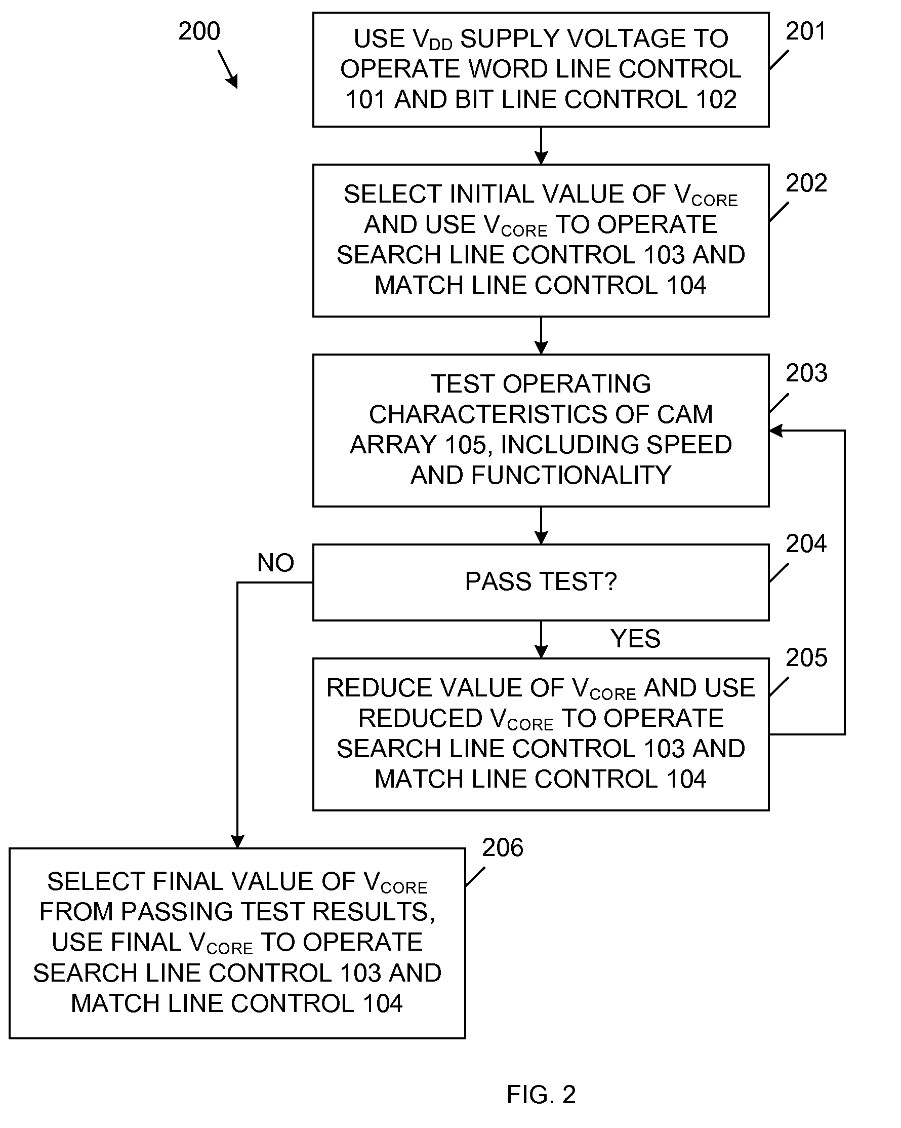
[0006]Accordingly, the present invention reduces power requirements of a CAM system by limiting the voltage swing of signals transmitted on the search lines and / or the match lines of the CAM array using an external CAM core power supply for search line and / or match line related circuits. The external CAM core power supply allows a user to easily adjust the voltage swing in the search line and / or match line related circuits, thereby adjusting trade-offs between operating speed / reliability and power consumption. By supplying the search line and / or match line related circuits from a power supply located external to the chip that includes the CAM array, the voltage swing can be safely and easily adjusted in a real silicon device.

Problems solved by technology

The majority of the power consumption within a CAM array results from signal switching on the search lines and the match lines coupled to the CAM cells.
However, circuits that produce low voltage output signals, such as pulse-width generators and charge pumps, can be complicated and difficult to control.
Moreover, circuits capable of receiving the low voltage signals as inputs, such as specialized sense amplifiers, can also be complicated and consume more power than necessary.
While it is desirable to minimize the voltage swing on the search lines and match lines to reduce power consumption, if this voltage swing is reduced too low, then the CAM array will fail to operate reliably.
It is difficult to measure in simulations how low the voltage swing can be reduced without resulting in failure of the CAM array.
If the voltage swing is reduced too much, such that CAM failure occurs, then the CAM array must be re-designed (and re-fabricated).
Conversely, if the voltage swing is reduced too little, then the CAM array will exhibit unnecessarily high power consumption.

Method used


Image

  • Separate CAM core power supply for power saving
  • Separate CAM core power supply for power saving
  • Separate CAM core power supply for power saving

Examples


Embodiment Construction

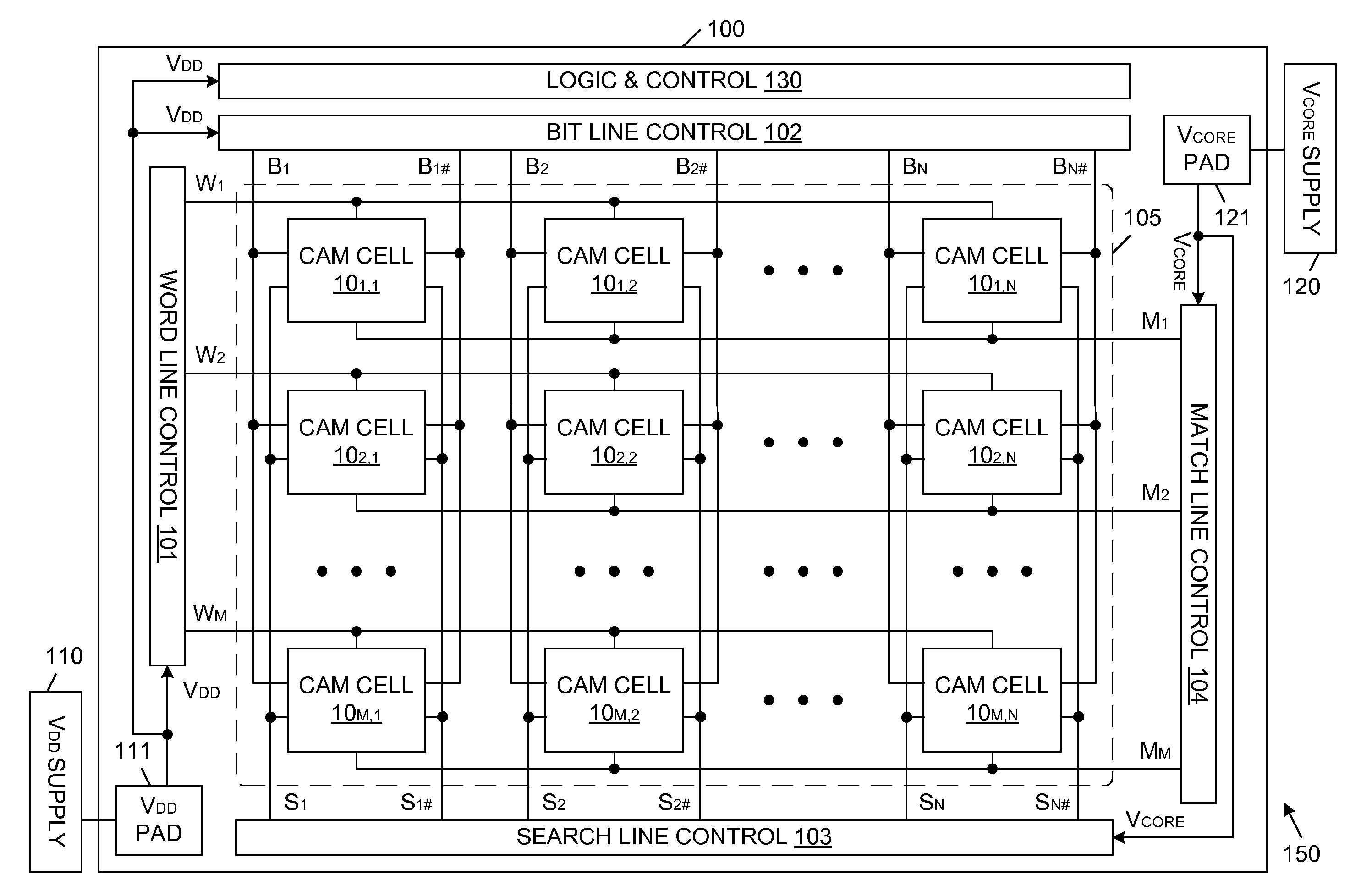
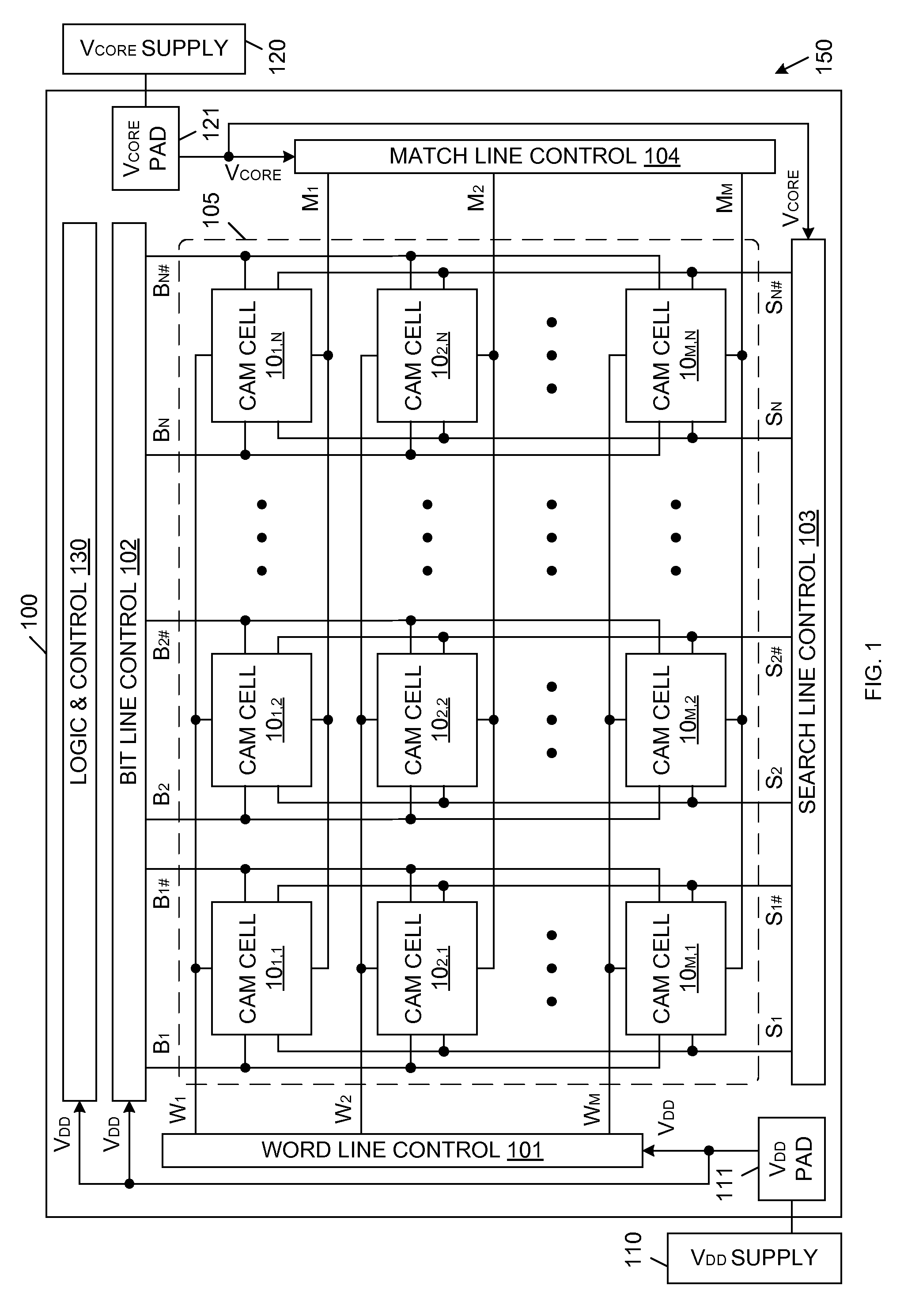
[0011]FIG. 1 is a block diagram of a CAM system 150 in accordance with one embodiment of the present invention. CAM system 150 includes a CAM device 100, an external VDD voltage supply 110 and an external VCORE voltage supply 120. CAM device 100 can be, for example, a packaged integrated circuit die (chip), which is fabricated using conventional semiconductor processing techniques.

[0012]CAM device 100 includes word line control circuit 101, bit line control circuit 102, search line control circuit 103, match line control circuit 104, CAM array 105, VDD supply pad 111, VCORE supply pad 121 and logic & control circuitry 130. In general, logic & control circuitry 130 includes conventional circuitry that may support or supplement CAM array 105 and the associated control circuits 101-104.

[0013]CAM array 105 includes M rows and N columns of CAM cells. Each CAM cell in CAM array 105 is labeled 10R,C, wherein R is the row number of the cell, and C is the column number of the cell. Thus, arr...


PUM


Abstract

A CAM system includes an integrated circuit chip having: logic & control circuitry, a CAM cell array, read / write access circuitry that performs read and write accesses to the CAM cell array, comparison access circuitry that performs comparison operations to the CAM cell array, a first voltage supply pad coupled to the read / write access circuitry; and a second voltage supply pad coupled to the comparison access circuitry. A first voltage supply, external to the integrated circuit chip, provides a first supply voltage to the first voltage supply pad, wherein the logic & control circuitry is powered by the first supply voltage. A second voltage supply, external to the integrated circuit chip, provides a second supply voltage to the second voltage supply pad, wherein at least a portion of the comparison access circuitry is powered by the second supply voltage, wherein the second supply voltage is less than the first supply voltage.

Description

FIELD OF THE INVENTION[0001]The present invention relates to content addressable memory (CAM) arrays. More specifically, the present invention relates to a system and method for reducing power consumption with CAM arrays.RELATED ART[0002]The majority of the power consumption within a CAM array results from signal switching on the search lines and the match lines coupled to the CAM cells. In general, a search operation involves pre-charging a plurality of match lines, wherein each match line is associated with a corresponding row of the CAM array. Search data is applied to search lines of the CAM array, wherein each search line or search line pair is associated with a corresponding column of the CAM array. A match line is discharged to indicate a non-matching condition if the data stored in the corresponding row of CAM cells does not match the applied search data.[0003]Providing a low voltage swing on the search lines and match lines reduces power consumption within the CAM array. Ho...

Claims


Application Information

Patent Timeline
Patent Type & Authority Patents(United States)
IPC IPC(8): G11C15/00
CPCG11C5/147G11C15/00G11C29/028G11C29/021G11C29/02
Inventor CHU, SCOTTPARK, KEE
Owner AVAGO TECH INT SALES PTE LTD
Learn More