
Method and apparatus for compensating for variations in particle trajectories in electrostatic sorter for flowcell cytometer

a flow cell cytometer and electrostatic sorter technology, applied in the field of flow cell cytometer systems, can solve the problems of increasing the dilution of particles, fixing delays, and reducing the purity of sorted populations, so as to improve the purity of sorted samples, reduce dilution, and facilitate the speed of particle travel

Active Publication Date: 2010-04-06
BECKMAN COULTER INC
View PDF3 Cites 38 Cited by
  • Summary
  • Abstract
  • Description
  • Claims
  • Application Information

AI Technical Summary

Benefits of technology

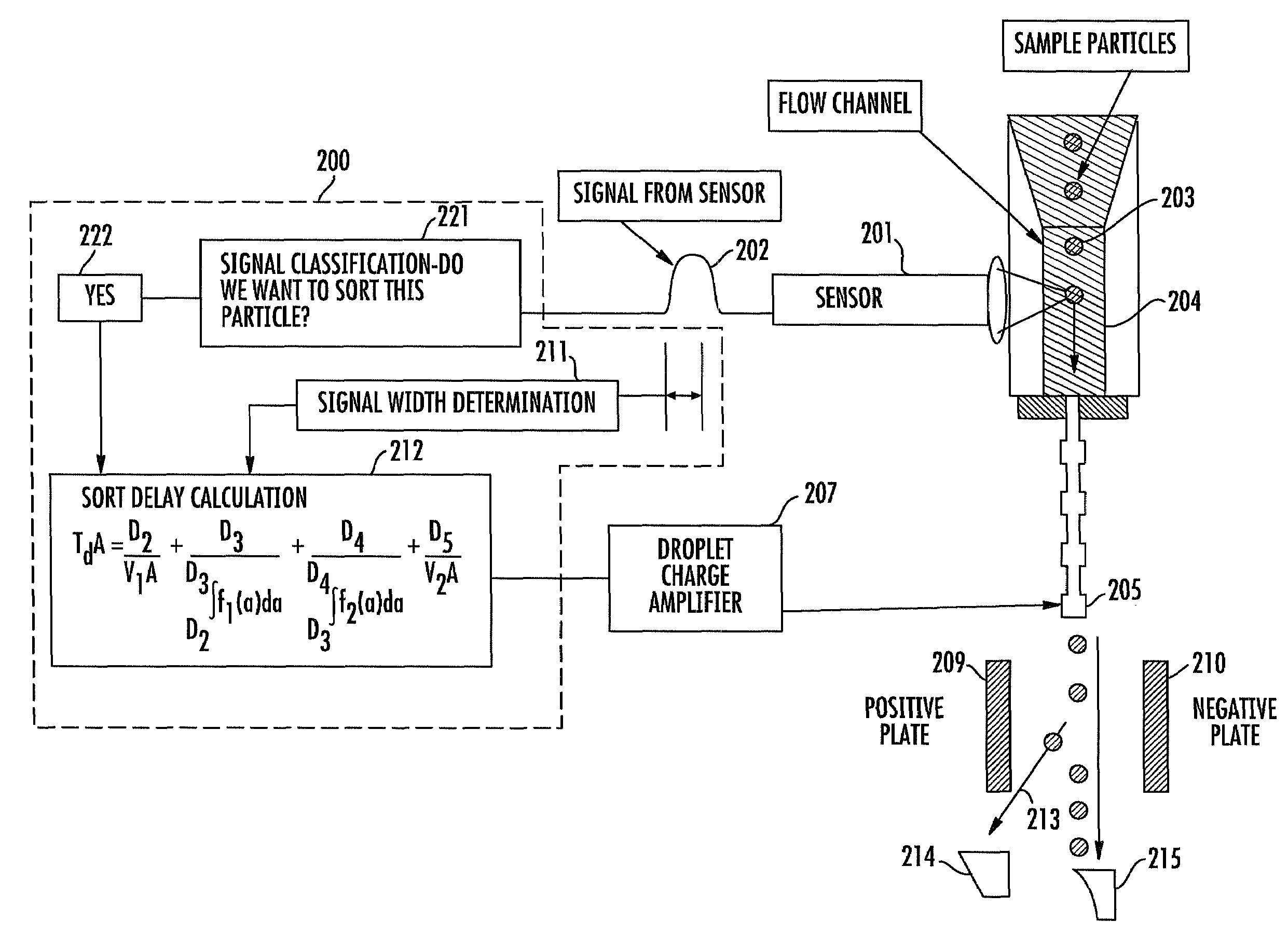
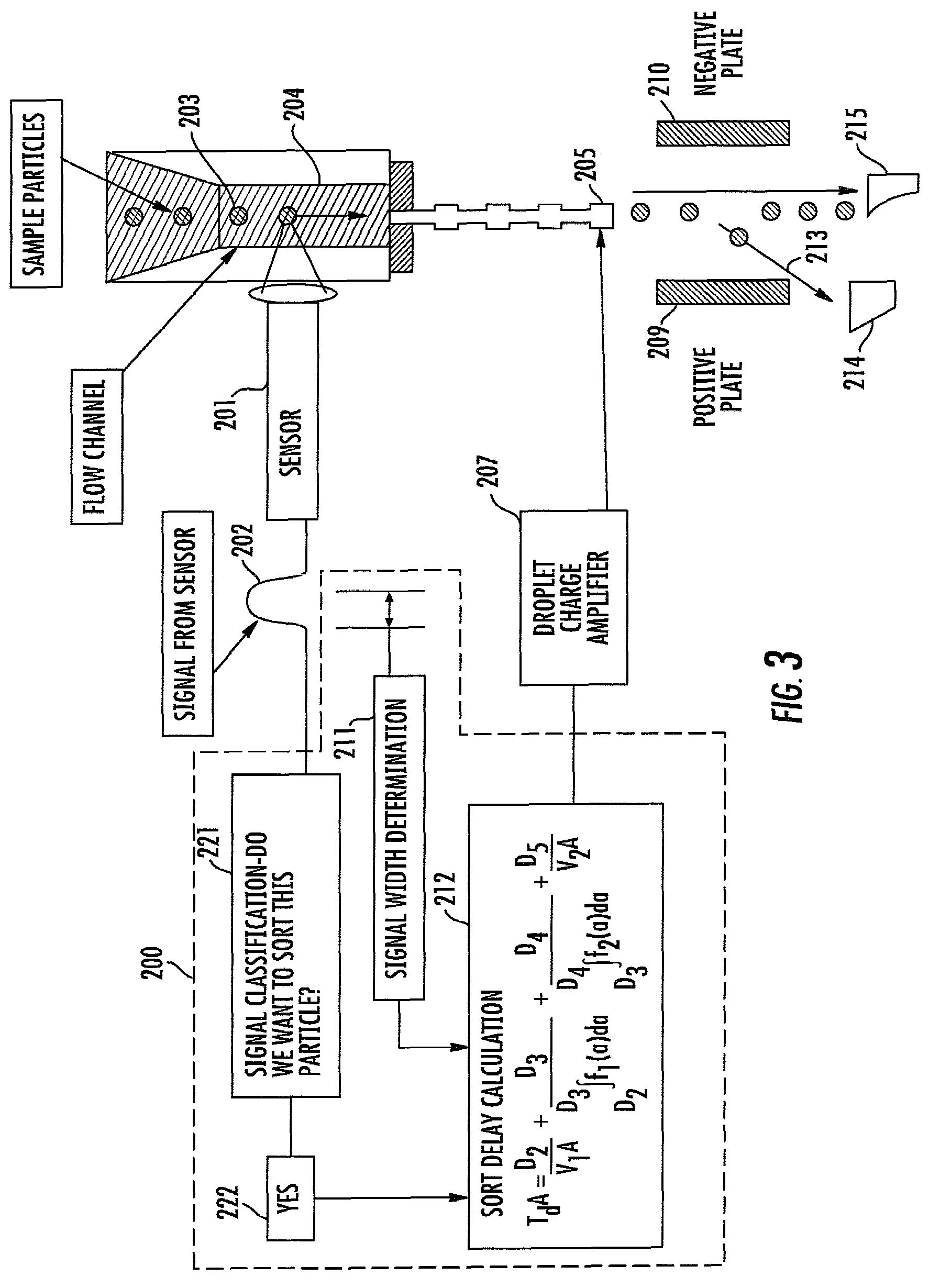
The present invention is a flow cytometer that uses the measured velocity of particles in a carrier fluid to compensate for different trajectories of particles through a sensing zone and in a fluid flow chamber. This allows for a more accurate analysis of the particles and reduces the dilution of the sample. The speed of travel of particles can be measured using laser beams and the width of the particle's pulse can be determined. The width of the pulse is indicative of the particle's trajectory and its velocity through the fluid flow chamber. The sort delay is calculated based on the particle's velocity and the geometry parameters of the fluid flow system. The invention improves the purity of the sorted sample and reduces the time it takes to sort the particles.

Problems solved by technology

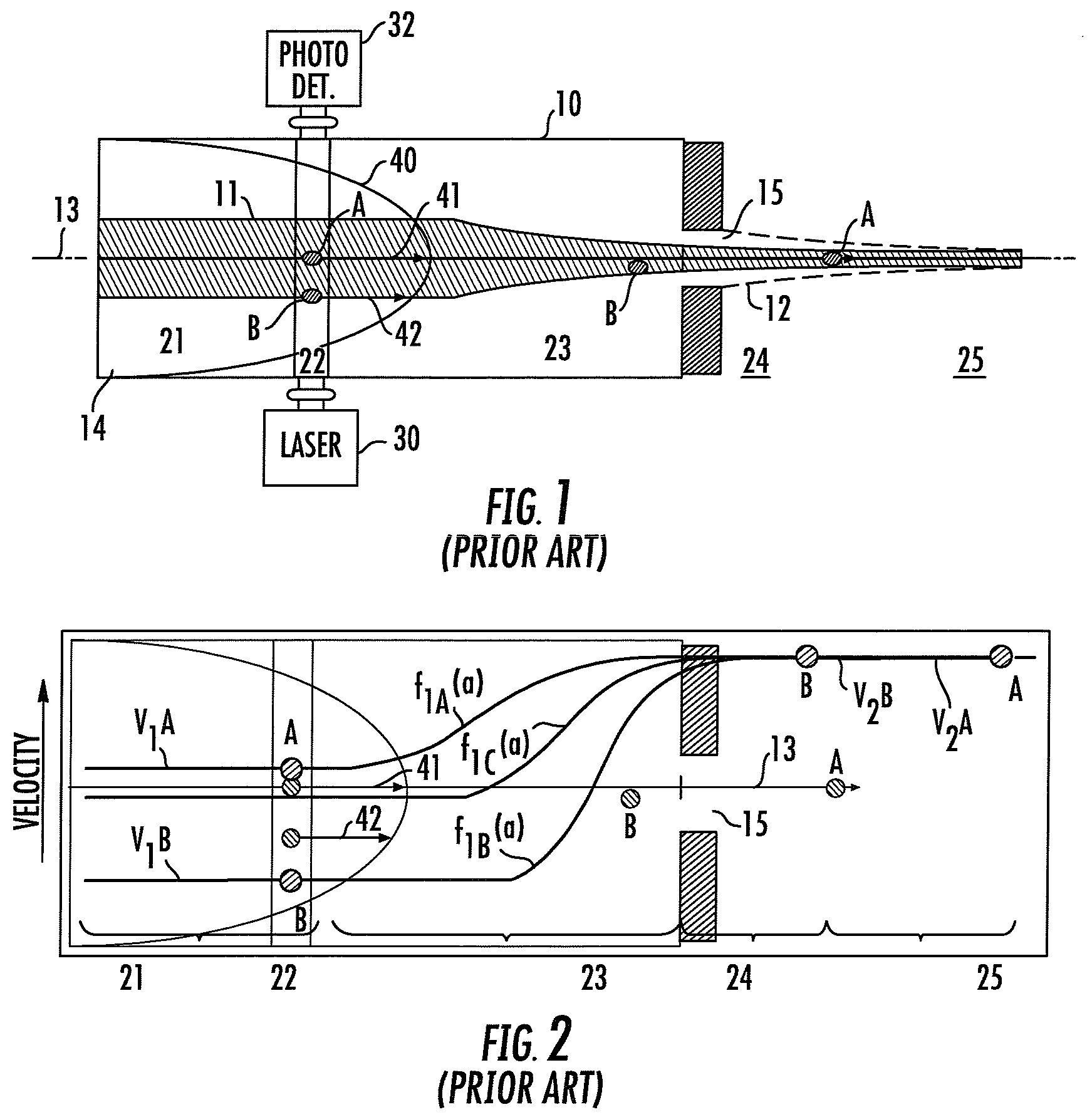
The use of a fixed delay constitutes a source of error in the charging / sorting operation due to the fact that not all particles travel at the same effective speed along the transport direction of the fluid, due to the fact that not all particles traverse the same trajectory through the flow chamber.
In an attempt to deal with this problem, conventional systems sort more than one droplet; this, in turn, decreases the purity of the sorted populations and increases the dilution of the particles.

Method used


Image

  • Method and apparatus for compensating for variations in particle trajectories in electrostatic sorter for flowcell cytometer
  • Method and apparatus for compensating for variations in particle trajectories in electrostatic sorter for flowcell cytometer
  • Method and apparatus for compensating for variations in particle trajectories in electrostatic sorter for flowcell cytometer

Examples


Embodiment Construction

[0026]Before detailing the architecture and methodology for compensating for variations in particle trajectories in a flowcell cytometer having an electrostatic sorter in accordance with the present invention, it should be observed that the invention resides primarily in a prescribed novel arrangement of conventional analog and digital circuits and components. Consequently, the configurations of such circuits and components and the manner in which they may be interfaced with a cytometer fluid flow chamber and an associated particle droplet charging unit have, for the most part, been shown in the drawings by readily understandable schematic block diagrams, which show only those specific aspects that are pertinent to the present invention, so as not to obscure the disclosure with details which will be readily apparent to those skilled in the art having the benefit of the description herein. Thus, the schematic block diagrams are primarily intended to show the major components of vario...


PUM

PropertyMeasurementUnit
lengthaaaaaaaaaa
widthaaaaaaaaaa
time delayaaaaaaaaaa

Abstract

A flow cytometer subsystems monitors a particle sensing zone within a fluid transport chamber for the presence of a particle (e.g., blood cell) traveling therethrough, and produces an output pulse, whose width is representative of the trajectory and thereby the length of time that the particle is within the particle sensing zone as it travels through the fluid transport chamber. This output pulse is then processed in accordance with geometry parameters of successive time delay zones of the particle fluid transport chamber through which the particle passes, in order to derive a composite time delay between the sensing of the particle to the time at which a fluid droplet containing the particle will break off from the carrier fluid. The composite time delay is employed to accurately establish the time at which the particle is controllably charged as the particle breaks off from the carrier fluid.

Description

FIELD OF THE INVENTION[0001]The present invention relates in general to flow cytometer systems and subsystems thereof, and is particularly directed to a new and improved signal processing and control mechanism therefor, that is operative to monitor a particle sensing zone within a fluid transport chamber for the presence of a particle (e.g., blood cell) traveling therethrough, and to produce an output pulse, whose width is representative of the trajectory and thereby the length of time that the particle is within the particle sensing zone as it travels through the fluid transport chamber. This output pulse is then processed in accordance with geometry parameters of successive time delay zones of the particle fluid transport chamber through which the particle passes, in order to derive a composite time delay between the sensing of the particle to the time at which a fluid droplet containing the particle will break off from the carrier fluid. The composite time delay is employed to ac...

Claims


Application Information

Patent Timeline
Patent Type & Authority Patents(United States)
IPC IPC(8): G01N33/48
CPCG01N15/1404G01N15/1427G01N2015/149G01N2015/1406G01N15/1459G01N15/149
Inventor FRAZIER, ERICH H.LARY, TODD P.
Owner BECKMAN COULTER INC
Learn More