
Chain lock for round steel chains

a technology for chain locks and steel chains, applied in the direction of driving chains, chain fastenings, shackles, etc., can solve the problems of affecting the load-bearing capacity of the chain lock by the bottom of the tank, so as to improve the load-bearing capacity of the chain lock and the effect of minimal bending moments

Inactive Publication Date: 2010-04-06
THIELE GMBH & CO KG
View PDF12 Cites 4 Cited by
  • Summary
  • Abstract
  • Description
  • Claims
  • Application Information

AI Technical Summary

Benefits of technology

The invention is a chain lock for round steel chains that can withstand higher load stresses and prevent shearing of the lock halves under load stress. The chain lock has two lock halves with a coupling section in between them. The coupling section has a pocket with linear outer flanks that face each other. The pocket has a web-like projection with a locking pin that can engage with the fork leg of the other lock half. The configuration of the pocket and the engagement areas of the fork leg maximize the load-bearing capacity of the chain lock. The chain lock is advantageously designed to absorb longitudinal forces and minimize bending moments. The flanks of the pocket and the engagement areas of the fork leg do not touch each other, but instead have play to improve the load-bearing capacity. The chain lock can be assembled and disassembled easily.

Problems solved by technology

Experiments have shown that the configuration of the projection and / or the flanks substantially affects the load-bearing capacity of the chain lock because the projection can shear off at high load stress under the influence of the transverse forces.
Very small projections as well as greatly protruding projections have proven to be disadvantageous.

Method used


Image

  • Chain lock for round steel chains
  • Chain lock for round steel chains
  • Chain lock for round steel chains

Examples


Embodiment Construction

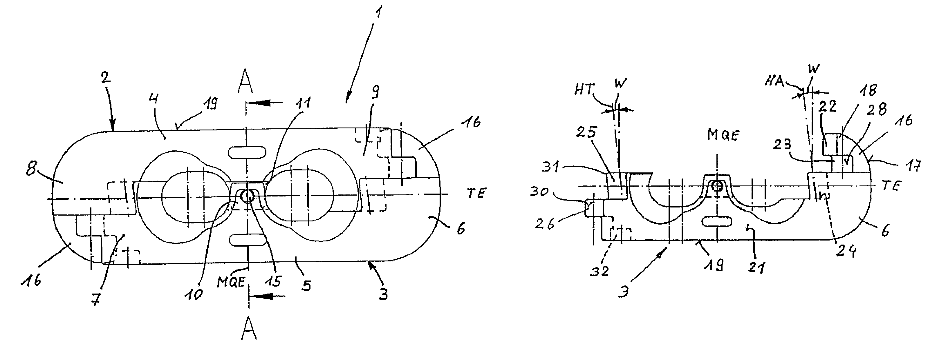
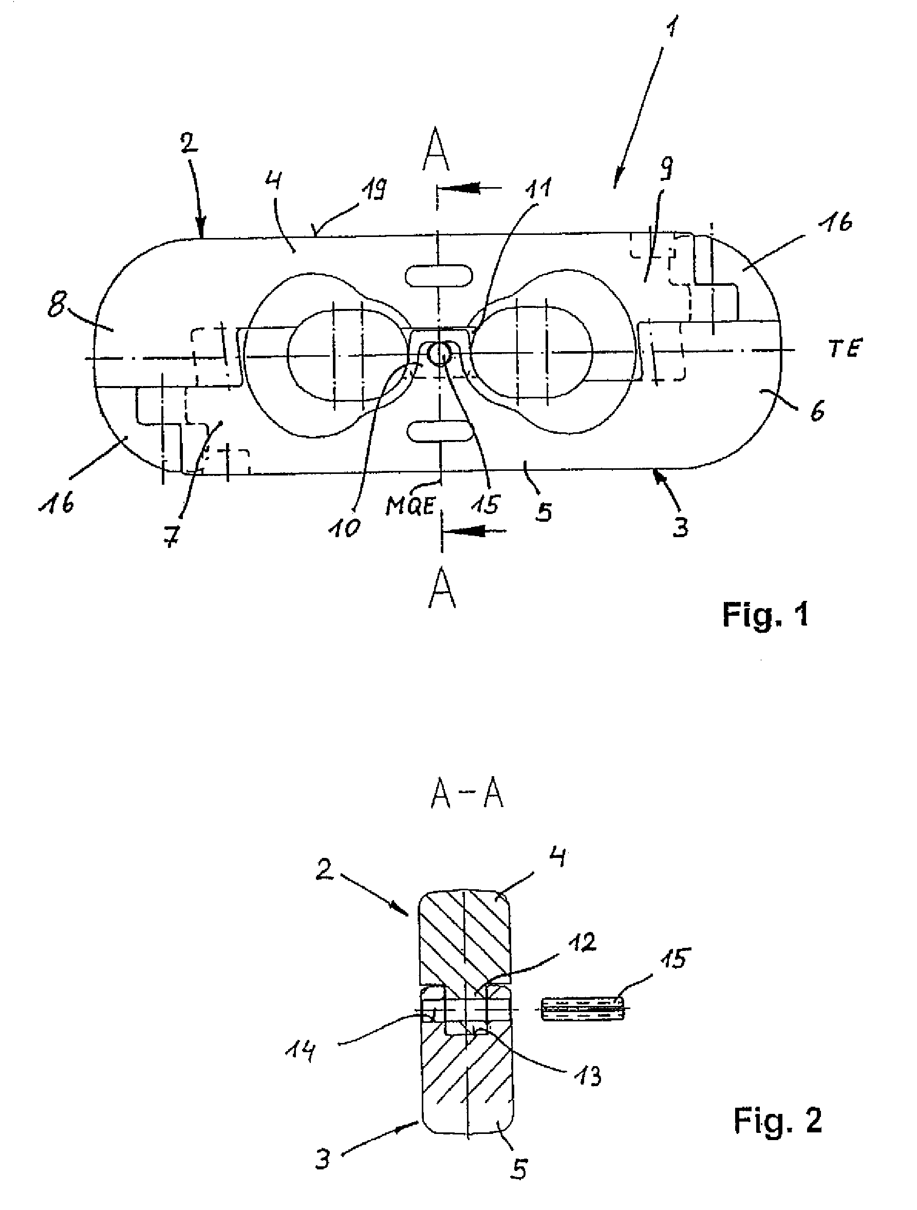
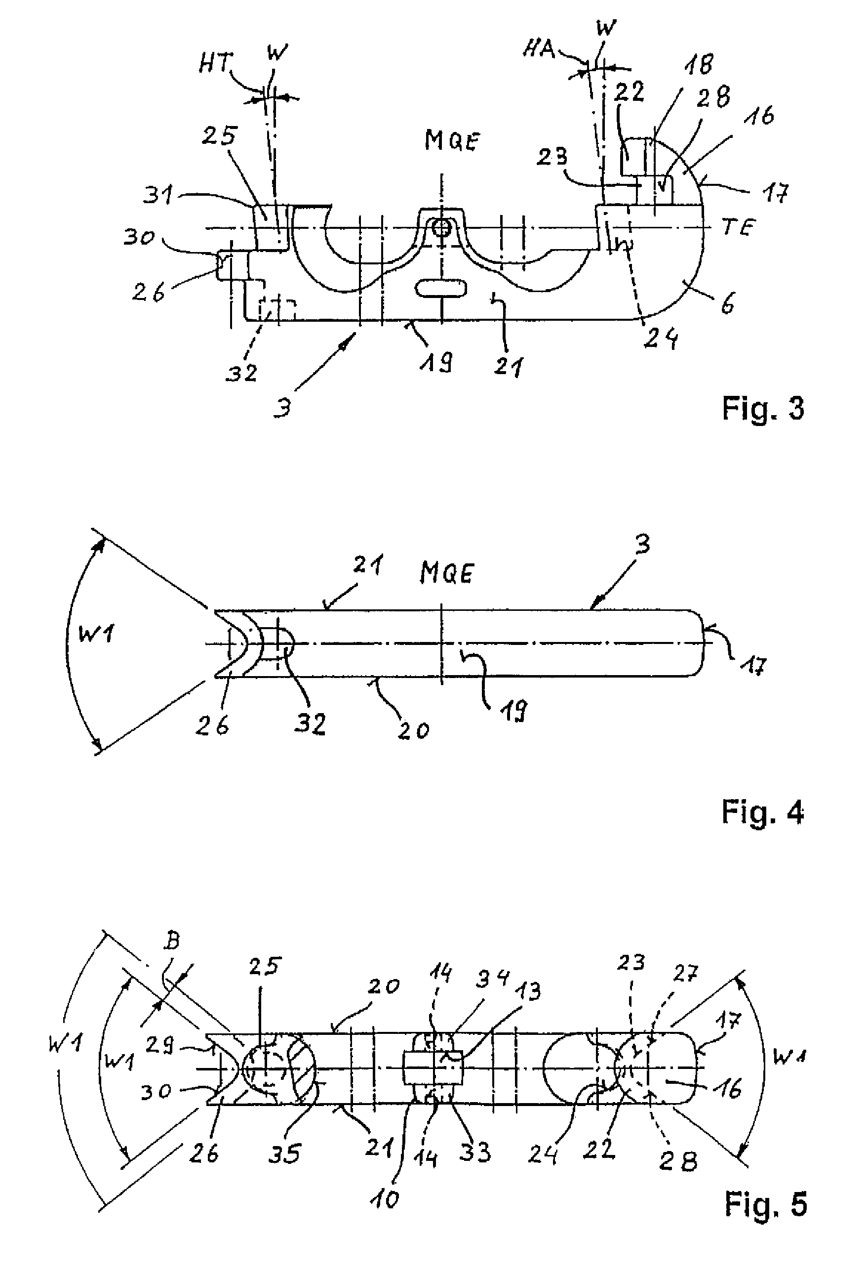
[0022]FIG. 1 shows a chain lock 1 having two substantially L-shaped lock halves 2, 3. Each of the lock halves 2, 3 has rear sections 4, 5 that extend in the longitudinal direction, i.e., in the direction of their parting plane TE-TE, and terminate in coupling sections 6, 7, 8, 9.

[0023]The rear sections 4, 5 of the lock halves 2, 3 have center supports 10, 11, via which the rear sections 4, 5 are supported with respect to each other so that a central necking of the chain lock 1 under tensile loading is avoided. FIG. 2 shows a sectional view along line A-A, i.e., along the transverse middle plane MQE of the chain lock 1, with a tongue 12 of the upper lock half 2 in the drawing plane engaging a groove 13 of the center support 11 of the lower lock half. A cross bore 14 is arranged in the area of the groove 13 and the tongue 12 for receiving a locking pin 15 in the form of a tension pin.

[0024]Besides the configuration of the center support 10, 11, the configuration of the coupling sectio...


PUM


Abstract

Disclosed is a chain lock for round steel chains, comprising two lock halves, each of which is provided with a rear section (4, 5) that extends in the longitudinal direction of the chain lock (1) as well as coupling sections (6 to 9) that adjoin the ends of the rear section (4, 5). One respective coupling section (6, 8) is fitted with a locking pin (16) which extends perpendicular to a parting plane (TE) of the chain lock (1) and encompasses a web-like projection (22) at the free end (18) thereof, on the side facing the other coupling section (7, 9). The projection (22) borders a pocket that extends from one side surface (20) to another side surface (21) of the lock half (2, 3) and accommodates a forked leg (26) of the other lock half (2, 3), which conforms to the contour of the pocket (23). The pocket (23) has external, essentially rectilinear flanks (27, 28) which face the side surfaces (20, 21), the angle (W1) enclosed by the flanks (27, 28) ranging from 120° to 150°.

Description

BACKGROUND OF THE INVENTION[0001]The invention relates to a chain lock for round steel chains.[0002]In the state of the art, DE 197 43 025 C1 discloses a block connecting link for round steel chains having two identical link halves. Each link half has a substantially rectangular cross-section with a straight rear surface, plane side surfaces, convexly curved end surfaces, and receptacles for steel chain links located next to the transverse middle plane and facing the center parting plane. Provided on one end of each link half is a projection having a bracket protruding towards the neighboring end surface, and provided on the other end is a projection having a recess that conforms to the bracket. A pin protrudes at the projection having the recess for engagement into a pocket next to the projection. The principal axes of the bracket, recesses, pins and pockets extend at an angle in relation to the transverse middle plane. A supporting cam is provided between the receptacles of each l...

Claims


Application Information

Patent Timeline
Patent Type & Authority Patents(United States)
IPC IPC(8): F16G15/02F16G15/04
CPCF16G15/04F16G15/02Y10T70/50
Inventor MULLE, WILHELM
Owner THIELE GMBH & CO KG
Learn More