Method for direct-oxygenation of alkane gases

a technology of alkane gas and direct oxygenation, which is applied in the direction of oxygen-containing compound preparation, ether preparation, transportation and packaging, etc., can solve the problems of low efficiency of process, and low efficiency of process

Active Publication Date: 2010-03-30
GAS TECH
View PDF138 Cites 16 Cited by
  • Summary
  • Abstract
  • Description
  • Claims
  • Application Information

AI Technical Summary

Problems solved by technology

This technology is energy intensive and the process economics are unfavorable for all but very large scale methanol plants.
However, in order to realize this process it is necessary to provide complicated equipment, to satisfy high requirements for the purity of the gas, to spend high quantities of energy for obtaining the synthesis gas and for its purification, and to have a significant number of intermittent stages from the process.
Also, for medium and small enterprises with the capacity of less than 2,000 tons / day it is not economically feasible.
In this apparatus, however, fast withdrawal of heat from the highly exothermic oxidation reaction of the hydrocarbon-containing gas in not achievable because of the inherent limitations of the heat exchanger.
This leads to the need for reduction in the quantity of supplied hydrocarbon-containing gas and, further, it reduces the degree of conversion of the hydrocarbon-containing gas.
Moreover, even with the use of oxygen as an oxidizer, it is not possible to provide an efficient recirculation of the hydrocarbon-containing gas due to the rapid increase of the concentration of carbon oxides.
A significant part of the supplied oxygen is wasted for oxidation of CO into CO2, and thereby additionally reduces the degree of conversion of the initial hydrocarbon-containing gas to useful products and provides a further overheating of the reaction mixture.
Since it is necessary to cool the gas-liquid mixture after each reactor for separation of liquid products and subsequent heating before a next reactor, the apparatus is substantially complicated and the number of units is increased.
Unfortunately, up until now, the per pass yields have been limited.
This limited yield has been rationalized as resulting from the low reactivity of the C—H bonds in methane vis-a-vis the higher reactivity of the primary oxygenated product, methanol, which results in selective formation of the deep oxidation products CO and CO2 when attempts are made to increase conversion.”
Unfortunately, laboratory results regarding methanol selectivity and single pass yield for non-catalyzed direct oxygenation of methane to methanol have not been reliably duplicated in scaling the reaction technology to manufacturing-sized systems.
The need for an efficient and low cost method for enabling non-catalyzed direct oxygenation of methane to methanol continues to be unfulfilled.

Method used


Image

  • Method for direct-oxygenation of alkane gases
  • Method for direct-oxygenation of alkane gases
  • Method for direct-oxygenation of alkane gases

Examples


embodiment 900

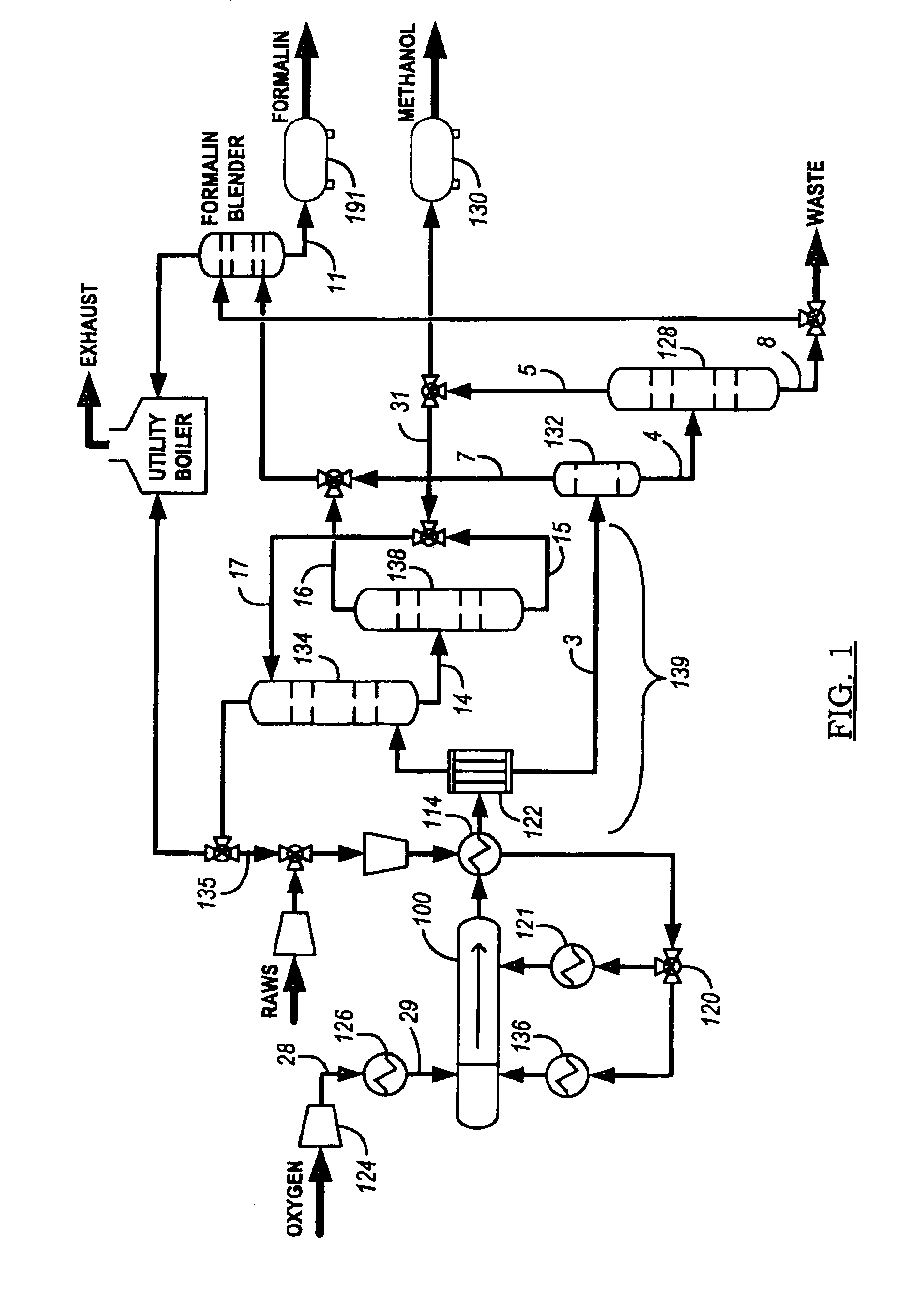
[0091]Another process embodiment 900 is presented in FIG. 9. Air 902 is input to compressor 934 and then cooled in heat exchanger 904 for delivery to one of nitrogen separator 906 or nitrogen separator 908. Oxygen feed is stored in tank 962 and compressed with compressor 910 for introduction as an oxygen-containing feed stream into reactor system 914 after heating in heater 912. Alkane-containing raw feed 926 (at least one C1-C4 alkane, primarily methane or natural gas) is compressed in compressor 928 and blended with scrubber 920 alkane recycle for further pressurization in compressor 922 and thermal cross exchange with reactor product stream reactor 936 in heat exchanger 930. The recycle stream preferably provides a weight percentage proportion of from about 4:5 to about 20:21 of alkane in the alkane-containing feed stream to reactor 914. In one embodiment, where scrubber 920 is pressurized to a pressure on the order of reactor system 914 (see FIGS. 12 to 24B and the accompanying ...

embodiment 1000

[0092]FIG. 10 shows another process embodiment 1000 with a front end process loop essentially similar to process 900 presented in FIG. 9, but incorporating an in-situ distillation system 1002 for separating methanol in steam 1004 (for absorbent in the scrubber), purified water in stream 1006 for use in knockdown drum 1012, and generation of purified methanol 1008 and waste stream 1010. Knockdown drum 1012 provides initial separation of liquid from the reactor product stream prior to the introduction of the remainder of the reactor product stream into the scrubber.

embodiment 1100

[0093]FIG. 11 presents process embodiment 1100 for generating a methanol product stream and formaldehyde with a front end process loop essentially similar to process 900 presented in FIG. 9, but incorporating an in-situ formaldehyde distillation system 1110 and methanol distillation system 1108 to generate methanol product stream 1102. The stream from methanol distillation system 1108 cools formaldehyde distillation system 1110 overheads to separate carbon dioxide (product stream 1106) and formaldehyde (product stream 1104) in absorber-blender 1116. A recycle stream of methanol to the scrubber is drawn from methanol distillation system 1108 and chilled in chiller 1112 to provide a high-efficiency scrubber for condensing the reactor product stream. Furnace or thermal oxidizer 1114 oxidizes a purge to remove non-reactive inerts (e.g., without limitation, nitrogen) with some alkane (methane) from the reactor-scrubber process loop and thereby augment efficient use of the reactor.

[0094]W...


PUM

PropertyMeasurementUnit
temperaturesaaaaaaaaaa
temperatureaaaaaaaaaa
pressureaaaaaaaaaa

Abstract

A method for alkyl oxygenate (e.g., methanol) manufacture via partial oxidation of alkane (methane) uses an injectively-mixed backmixing reaction chamber in fluid communication with a tubular-flow reactor. Alkyl free radicals are induced in the backmixing reaction chamber prior to being fed through a flow-restriction baffle to the tubular-flow reactor. Injective intermixing of feed streams agitates the backmixing reaction chamber. In one embodiment, a variable position flow restriction baffle is axially moved to commensurately modify the backmixing reaction chamber and tubular-flow reactor volumes. In another embodiment, the tubular-flow reactor is quenched with a variable position quenching input. The method further provides for condensing the output stream from the reaction system in a condensing scrubber and also for recycling a portion of the scrubbed output stream to the reactor system.

Description

CROSS-REFERENCE TO RELATED APPLICATIONS[0001]This application is a divisional of U.S. patent application Ser. No. 11 / 685,867, filed Mar. 14, 2007, now U.S. Pat. No. 7,456,327 which is a continuation-in-part of International Applications PCT / US2007 / 004557, filed Feb. 19, 2007; PCT / US2007 / 004297, filed Feb. 19, 2007; and PCT / US2007 / 004185, filed Feb. 19, 2007. Each of International Applications PCT / US2007 / 004557; PCT / US2007 / 004297; and PCT / US2007 / 004185 is a continuation-in-part of U.S. application Ser. Nos. 11 / 526,824, filed Sep. 25, 2006; 11 / 446,371, filed Jun. 2, 2006; now abandoned 11 / 432,692, filed May 11, 2006; and 11 / 351,532, filed Feb. 10, 2006. Each of U.S. application Ser. Nos. 11 / 526,824; 11 / 446,371; 11 / 432,692; and 11 / 351,532 is a continuation- in-part of U.S. application Ser. No. 11 / 319,093, filed Dec. 27, 2005. The disclosures of the above applications are hereby incorporated by reference.BACKGROUND OF THE INVENTION[0002]The present invention relates to a method of react...

Claims


Application Information

Patent Timeline
Patent Type & Authority Patents(United States)
IPC IPC(8): C07C41/02C07C27/10
CPCB01F3/02B01F5/0451B01F5/0463B01F5/0682B01F5/0688B01J4/002B01J8/0221B01J19/0013B01J19/006B01J19/02B01J19/2405B01J19/2415B01J19/26C07C29/1518C07C29/50C07C31/04C07C31/08C07C31/10C07C31/12B01J2219/00006B01J2219/00038B01J2219/00051B01J2219/00119B01J2219/00162B01J2219/00765B01J2219/00768B01J2219/0077B01J2219/00772B01J2219/00777B01J2219/0209B01J2219/0245B01J2219/0286B01J2219/182B01J2219/1943B01J2219/1946B01F23/10B01F25/31331B01F25/3131B01F25/45B01F25/4521
Inventor PAWLAK, NATHAN A.CARR, ROBERT W.GRUNCH, ROGER J.
Owner GAS TECH
Why Eureka
Try Eureka