
Three legs clip for windshield (article support)

a technology of article support and three legs, applied in the direction of screws, lighting support devices, building scaffolds, etc., can solve the problems of lack of versatility of article support, uneven insertion of mount sections into mounting holes, and inability to maintain the engagement function and the load bearing function of the first and second engaging elements, so as to achieve the effect of improving the load bearing function and maintaining the engagement function

Active Publication Date: 2010-03-30
3M INNOVATIVE PROPERTIES CO
View PDF17 Cites 9 Cited by
  • Summary
  • Abstract
  • Description
  • Claims
  • Application Information

AI Technical Summary

Benefits of technology

The article support effectively prevents positional displacement and stress concentration on adhesive layers, enhances adaptability to positional errors, and simplifies attachment processes, ensuring stable and reliable temporary fixing of window glasses during automated operations.

Problems solved by technology

Therefore, this article support lacks versatility because the object, to which the article support is attached, must be provided with an abutment region for the presser section apart from the engagement position for the nail section even when this article support is used in applications other than the temporal fixing of the window glass.
Therefore, this article support also lacks versatility because the object, to which the article support is attached, must be provided with an abutment region for the spacer apart from the engagement position for the hooks.
However, if the article support is fastened to the window glass with some rotation with respect to the normal position or the mounting hole is formed on the vehicle body with some deviation from the normal contour, the mount section may not be inserted into the mounting hole smoothly and the engagement maintaining elements (the nail section and the hooks) of the mount section may not be engaged with the edge of the mounting hole stably.

Method used


Image

  • Three legs clip for windshield (article support)
  • Three legs clip for windshield (article support)
  • Three legs clip for windshield (article support)

Examples


Embodiment Construction

[0028]Hereinafter, exemplary embodiments of the present invention will be described with reference to the accompanying drawings. Throughout the several views, like elements are designated by like reference numerals.

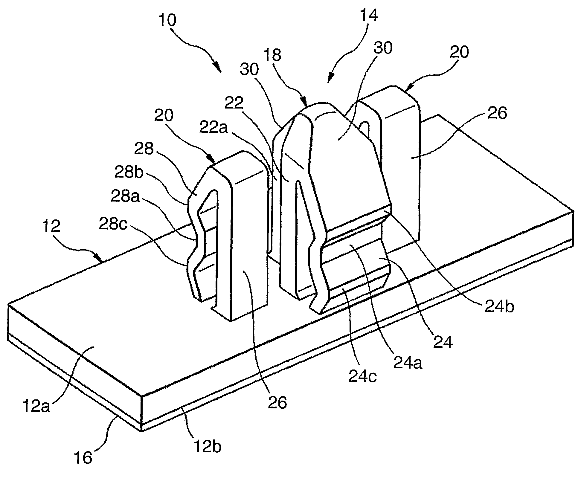
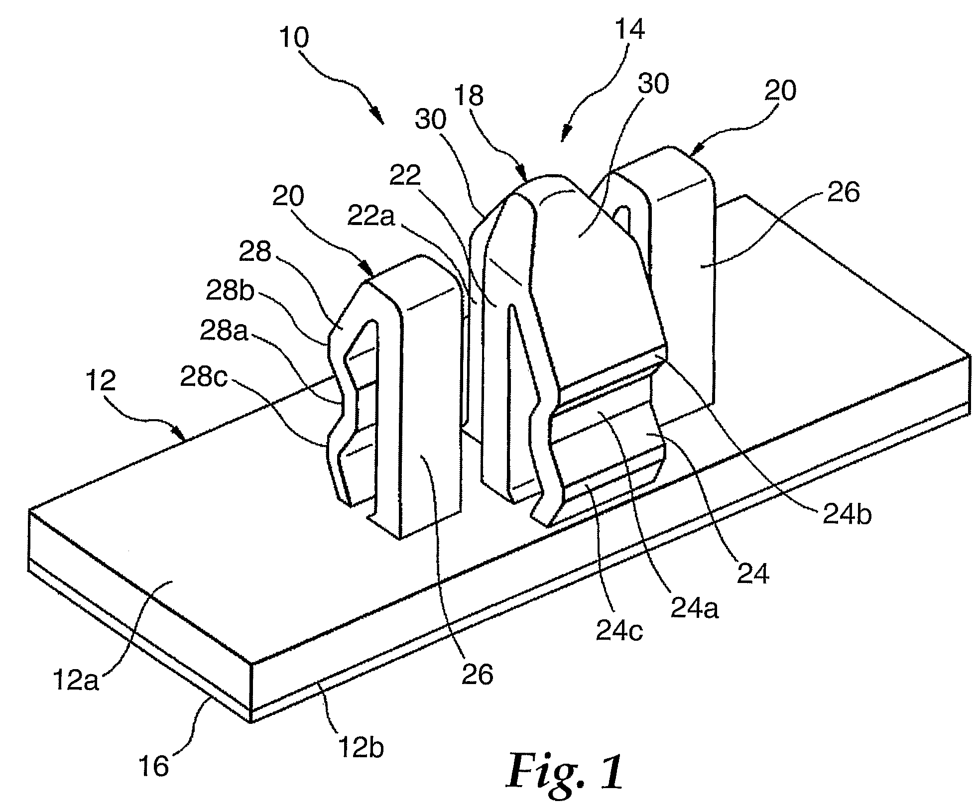
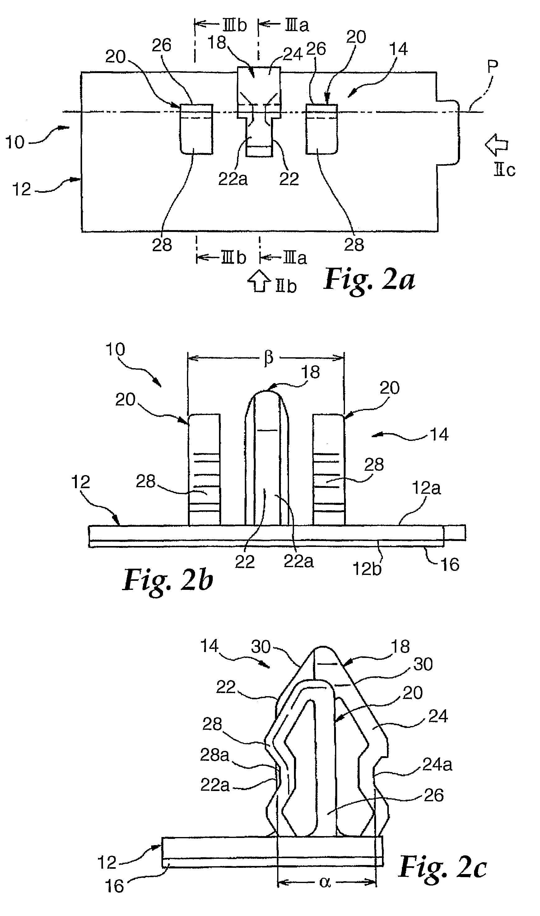
[0029]FIG. 1 is a perspective view of an article support 10 according to an embodiment of the present invention, FIGS. 2(a)-2(c) are a front view, a side view and a plan view of the article support 10, respectively, and FIGS. 3(a) and 3(b) are different cross-sectional views of the article support 10. The article support 10 comprises a base 12 and a mount section 14 provided on the base 12. The article support 10 having the base 12 and the mount section 14 is integrally formed of a resin material such as nylon, polybutylene terephthalate, polyacetal and the like.

[0030]The base 12 is a plate-like element that is rectangular when viewed from top and that has a top surface 12a and a back surface 12b, which are substantially flat and extend parallel to each other. An adhesive...


PUM


Abstract

An article support having a mount section comprising: a first engaging element (18) that has a pillar protruding from a base and a first hook extending from the pillar so that it can be displaced elastically; and a second engaging element that has a pillar protruding from the base and a second hook extending from the pillar so that it can be displaced elastically. The first hook and the second hook can be displaced elastically independently of each other and are disposed on the sides opposite to each other with respect to the pillars and. When the mount section is attached to an object, the pillar of the first engaging element bears a load on the object and the first hook and the second hook are engaged with the object to fixedly hold the article support on the object.

Description

FIELD OF THE INVENTION[0001]The present invention relates to an article support for supporting an article while the article support is fixedly attached to another object.BACKGROUND[0002]There is known an article support for supporting an article fastened to a base while a mount section provided on the base is attached to another object, wherein the mount section mainly bears any load on the object. Such article support can be used, for example, for temporal fixing while adhesive is being cured when a window glass for a car is bonded to a window frame of a car body.[0003]Japanese Unexamined Patent Publication (Kokai) No. 8-310233 discloses an article support used for temporal fixing of a window glass for a vehicle. This article support has: a base plate sticked on a window glass; a leg member standing on the base plate; and a nail section provided at a distal end of the leg member to be engaged with a vehicle body. When this article support is used, a mounting hole is formed at the e...

Claims


Application Information

Patent Timeline
Patent Type & Authority Patents(United States)
IPC IPC(8): E04G5/06B60J1/02F16B5/06F16B19/00F16B21/08
CPCF16B5/065F16B21/088F16B5/0664Y10T24/309
Inventor TORIGOE, SHINJIOSADA, KAZUTOMOYOSHIDA, HIDETOSHIMAEDA, YUKIHIROKAKUTA, ATSUSHINAKANUMA, ISAOINAGAKI, TAKAYOSHIFURUBETSUPU, KAZUYUKI
Owner 3M INNOVATIVE PROPERTIES CO
Learn More