Air conditioning system

a technology of air conditioning system and air temperature, which is applied in the direction of domestic cooling apparatus, lighting and heating apparatus, heating types, etc., can solve the problems of large proportion of ventilation heat load to the total amount of heat load to be treated in the air conditioning system, inability to reduce the ventilation heat load necessary for maintenance of iaq, and discomfort of the occupant in the room, so as to achieve comfortable room heating and increase the temperature level of room heating device.

Inactive Publication Date: 2010-03-30
DAIKIN IND LTD
View PDF24 Cites 3 Cited by
  • Summary
  • Abstract
  • Description
  • Claims
  • Application Information

AI Technical Summary

Benefits of technology

[0008]Therefore, an object of the present invention is to prevent, in an air conditioning system capable of heating the room, a decrease in the humidity in the room caused by the ventilation air that is supplied to the room for ventilation in the room.
[0034]In this air conditioning system, CO2 is used as the refrigerant that flows through the vapor compression type refrigerant circuit in the heat source unit, so that the refrigerant temperature on the discharge side of the compressor can be increased, and the temperature level that can be used in the room heating device can be increased. This will achieve comfortable room heating.

Problems solved by technology

This ventilation heat load will be treated by the room heating devices after the ventilation air is supplied to the room and mixed with indoor air, which consequently causes the room occupant to feel discomfort due to the supply of low temperature ventilation air (hereinafter referred to as a cold draft).
In such houses having high airtightness and high heat insulation properties, improved heat insulation properties can reduce the total amount of heat load; however, the ventilation heat load necessary for maintenance of IAQ cannot be reduced.
Therefore, the proportion of the ventilation heat load to the total amount of heat load to be treated in the air conditioning system is relatively large.
As a result, the humidity in the room will decrease, causing a problem that the room will be dry, when trying to ensure the required amount of ventilation in order to maintain the IAQ as described above.
In addition, when the above described type of a heat source unit that uses CO2 as the refrigerant is used, the temperature level that can be used in the room heating devices can be increased, however, the temperature difference between an inlet and an outlet of the utilization side heat exchanger will be reduced, resulting in a reduced coefficient of performance (hereinafter referred to as COP) of the heat source unit.

Method used


Image

  • Air conditioning system
  • Air conditioning system
  • Air conditioning system

Examples


example 1

(4) Modified Example 1

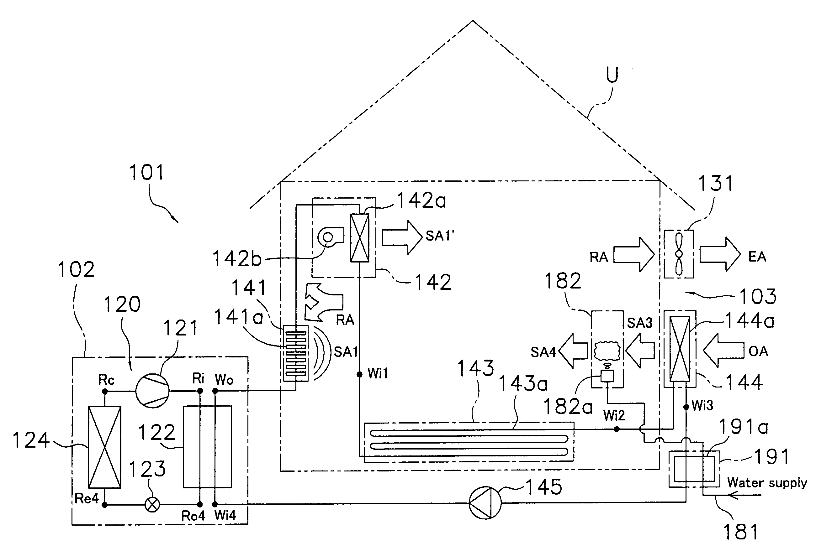
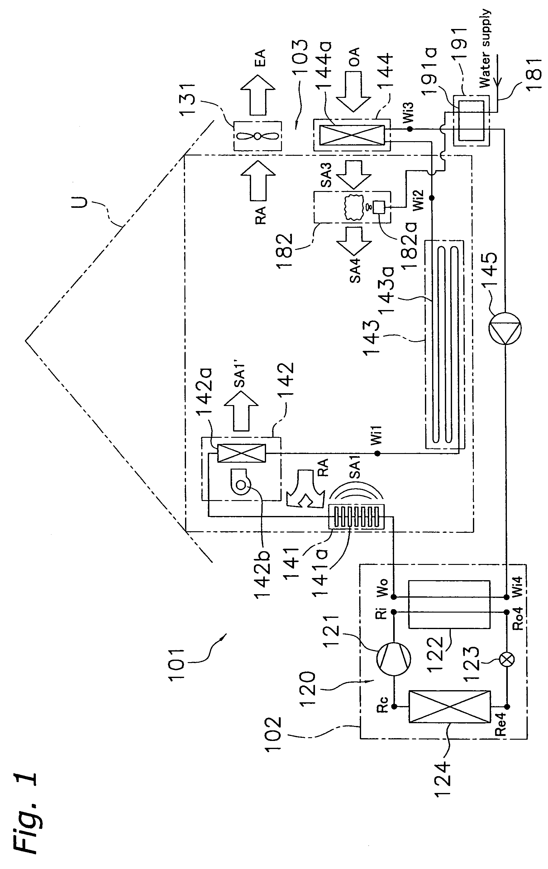
[0089]In the above described air conditioning system 101, the supply water heating device 191 is connected to the heating medium circuit 104 such that the heating medium whose temperature is the lowest as a result of releasing its heat in the radiator 141, the fan convector 142, the floor heating device 143 and the outdoor air heating heat exchanging device 144 is supplied, however, the supply water heating device 191 may be connected to the heating medium circuit 104 such that a high temperature heating medium that just has been heated in the heating medium—refrigerant heat exchanger 122 is supplied.

[0090]For example, in the air conditioning system 101 that does not include the fan convector 142 as shown in FIG. 7, the heating medium circuit 104 may be connected to the heating medium—refrigerant heat exchanger 122 such that the heating medium heated in the heating medium—refrigerant heat exchanger 122 is first supplied to the supply water heating device 191, a...

example 2

(5) Modified Example 2

[0093]In the above described air conditioning system 101, the supply water heating device 191 (or the first and second supply water heating devices 192, 193, when two heat exchangers are disposed) is connected to the heating medium circuit 104 and configured so as to heat water to be supplied to the humidifier 182 with the heat of the heating medium. However, the supply water heating device 191 (or the first and second supply water heating devices 192, 193, when two heat exchangers are disposed) may be connected to the refrigerant circuit 120.

[0094]For example, in the air conditioning system 101 that does not include the fan convector 142 as show in FIG. 9, the supply water heating device 191 may be connected to the refrigerant circuit 120 such that the refrigerant sent from the heating medium—refrigerant heat exchanger 122 to the expansion mechanism 123 is supplied. Also in this case, as in the air conditioning system 101 shown in FIG. 1, the radiator 141, the...

example 3

(6) Modified Example 3

[0098]A description was given of the configuration of the air conditioning system 101 shown in FIGS. 8 and 11 of the above described modified examples 1 and 2 in which both the first and second supply water heating devices 192, 193 are connected to either one of the heating medium circuit 104 and the refrigerant circuit 120. However, it is not limited thereto, and either one of the first and second supply water heating devices 192, 193 may be connected to the heating medium circuit 104, and the other one may be connected to the refrigerant circuit 120.

[0099]For example, in the air conditioning system 101 that does not include the fan convector 142 as shown in FIG. 12, the first supply water heating device 192 may be connected to the refrigerant circuit 120 such that the refrigerant sent from the compressor 121 to the heating medium—refrigerant heat exchanger 122 is supplied; the second supply water heating device 193 may be connected to the heating medium circu...


PUM


Abstract

An air conditioning system includes a heat source unit, an air supply device that supplies the outside air to the room as the ventilation air, a water supply type humidifier for humidifying the ventilation air, a heating medium circuit, and a supply water heating device. The heat source unit heats a heating medium that is used for heating the room in a heating medium—refrigerant heat exchanger. The heating medium circuit includes at least one room heating device that releases the heat of the heating medium heated in the heating medium—refrigerant heat exchanger into the room, and circulates the heating medium between the room heating device and the heating medium—refrigerant heat exchanger. The supply water heating device uses the heat generated from the heat source unit in order to heat water to be used in the humidifier.

Description

CROSS-REFERENCE TO RELATED APPLICATIONS[0001]This U.S. National stage application claims priority under 35 U.S.C. §119(a) to Japanese Patent Application No. 2004-134353, filed in Japan on Apr. 28, 2004, the entire contents of which are hereby incorporated herein by reference.TECHNICAL FIELD[0002]The present invention relates to an air conditioning system. More specifically, the present invention relates to an air conditioning system capable of heating the room.BACKGROUND ART[0003]As an air conditioning system capable of heating the room, conventionally known is a system configured by connecting room heating devices such as a radiator and a fan convector to a heat source unit having a vapor compression type refrigerant circuit (for example, see Japanese Patent Application Publication Nos. 2003-50035, 2003-172523 and 2003-50050). Such an air conditioning system heats the room by heating the floor and indoor air.[0004]In addition, as a heat source unit of such an air conditioning syste...

Claims


Application Information

Patent Timeline
Patent Type & Authority Patents(United States)
IPC IPC(8): F25B13/00F24D3/00F24F3/044F24F5/00F24F6/04F24F6/14
CPCF24F3/044F24F5/0089F24F6/14F25B9/008F25B2309/061Y02B30/545Y02B30/54F24F5/00F24F6/04F24D3/00
Inventor YOSHIMI, MANABU
Owner DAIKIN IND LTD
Why Eureka
Try Eureka