Deformable mirror apparatus
a mirror and deformation technology, applied in the direction of mirrors, mountings, instruments, etc., can solve the problems of lowering detection accuracy and resolution, difficult deformation of the membrane part to a complicated shape (high-order shape), etc., and achieve the effect of small thermal expansion coefficien
- Summary
- Abstract
- Description
- Claims
- Application Information
AI Technical Summary
Benefits of technology
Problems solved by technology
Method used
Image
Examples
first embodiment
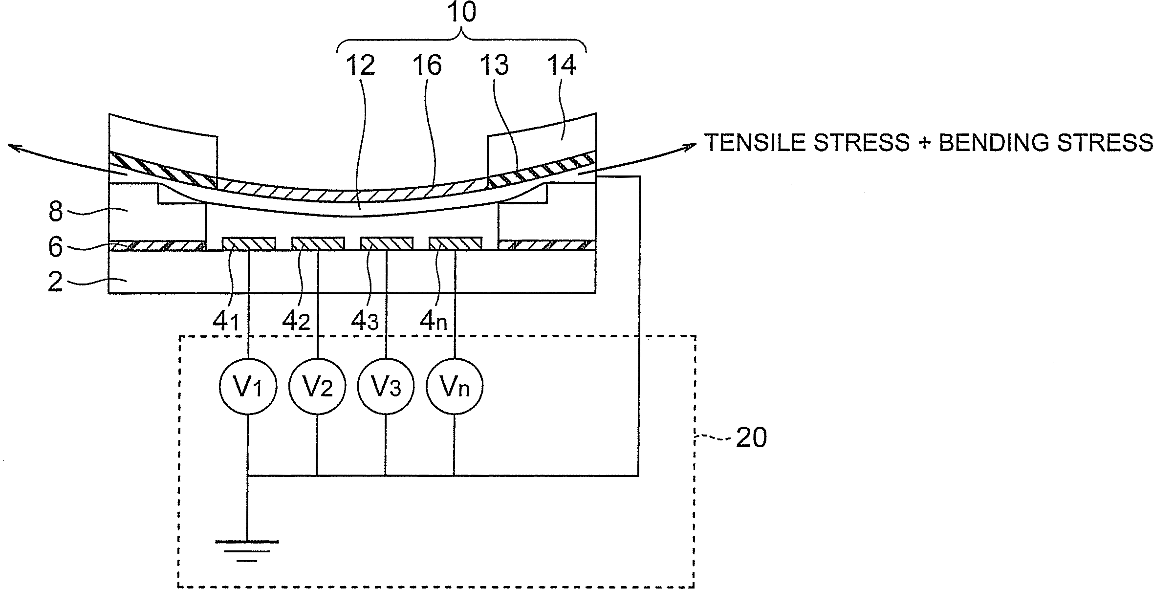
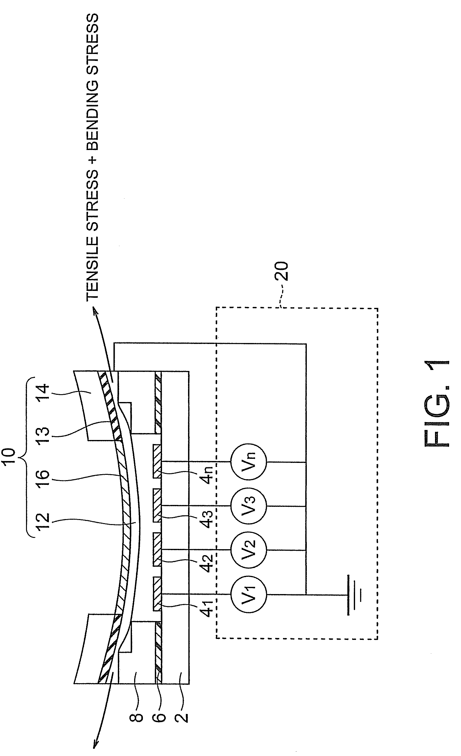
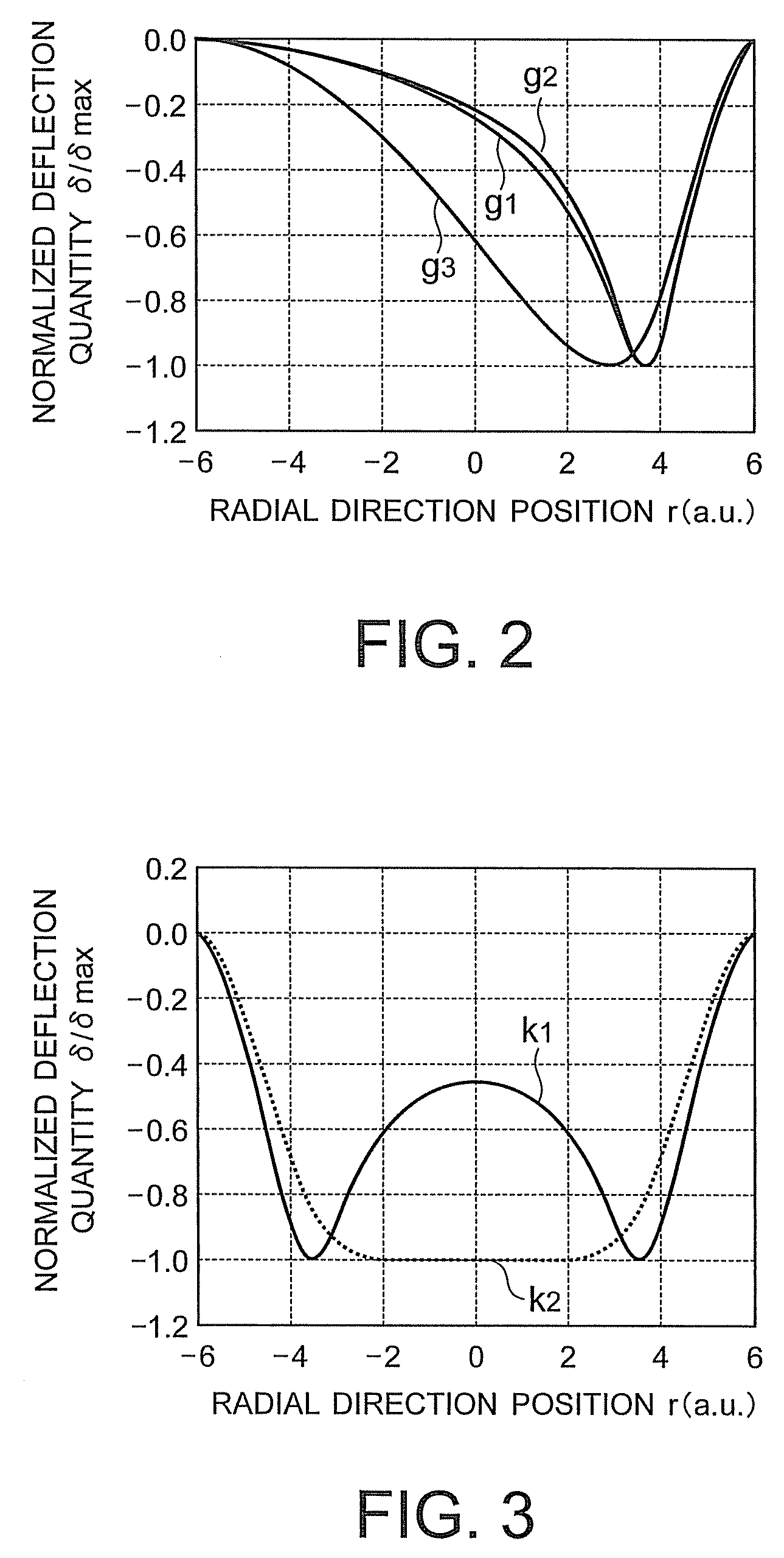
[0038]A deformable mirror apparatus according to a first embodiment of the present invention is shown in FIG. 1. In a deformable mirror apparatus according to the present embodiment, a plurality of electrodes 41 to 4n are formed on a laminated ceramic substrate 2. Furthermore, a spacer substrate 8 having an opening in its central part is provided on the laminated ceramic substrate 2. The spacer substrate 8 is bonded to the laminated ceramic substrate 2 by an adhesive agent 6 so as to dispose a plurality of electrodes 4 on the bottom part of the opening. A step (one step in FIG. 1) is provided on a surface of the spacer substrate 8 on the opposite side from the laminated ceramic substrate 2. A drive part 10 is provided on the surface of the spacer substrate 8 having the step. The drive part 10 includes a membrane part 12 disposed so as to be in contact with and cover the step and so as to be opposed to the electrodes 4, a casing part 14 which supports the membrane part 12 and which h...
second embodiment
[0060]A deformable mirror apparatus according to a second embodiment of the present invention is shown in FIG. 17.
[0061]The deformable mirror apparatus according to the present embodiment is formed by replacing the spacer substrate 8 in the first embodiment with a spacer substrate 9 (made of, for example, glass) which has a flat surface and which is smaller in thermal expansion coefficient than the membrane part 12 and the casing part 14 included in the drive part 10, and conducting anodic bonding with the drive part 10 under heating (at, for example, 350° C.). In a state in which voltages are not applied to the electrodes 41 to 4n in the deformable mirror apparatus according to the present embodiment, therefore, tensile stress and compressive stress caused by a thermal expansion coefficient difference act near the interface between the spacer substrate 9 and the membrane part 12. As a result, a change is caused in the boundary condition (fixing condition of the membrane part 12) an...
third embodiment
[0063]A deformable mirror apparatus according to a third embodiment of the present invention is shown in FIG. 18.
[0064]The deformable mirror apparatus according to the present embodiment has a configuration obtained from the configuration in the first embodiment shown in FIG. 1 by replacing the spacer substrate 8 with a spacer 7 and sticking a doughnut-shaped thin film piezoelectric actuator 40 on an opposite side of the membrane part 12 from the reflection film 16 (on a side opposed to the electrodes) or forming a film. The thin film piezoelectric actuator 40 is provided in a position where the operation of deforming the membrane part 12 by electrostatic sucking force is not interfered. By the way, the spacer 7 is bonded to the substrate 2 and the membrane part 12 by using an adhesive agent 6.
[0065]In the structure of the present embodiment, stress caused in the membrane part 12 when currents are let flow through the electrodes 41 to 4n and the membrane part 12 is calculated by usi...
PUM
 Abstract
Description
Claims
Application Information
 - R&D
- Intellectual Property
- Life Sciences
- Materials
- Tech Scout
- Unparalleled Data Quality
- Higher Quality Content
- 60% Fewer Hallucinations
Browse by: Latest US Patents, China's latest patents, Technical Efficacy Thesaurus, Application Domain, Technology Topic, Popular Technical Reports.
© 2025 PatSnap. All rights reserved.Legal|Privacy policy|Modern Slavery Act Transparency Statement|Sitemap|About US| Contact US: help@patsnap.com


