
Current-steering type digital-to-analog converter

a current-steering type, digital-to-analog converter technology, applied in the field of mixed signal circuits, can solve the problems of affecting the dynamic performance of the dac, forcing internal bias points to change,

Active Publication Date: 2010-03-16
BOARD OF RGT THE UNIV OF TEXAS SYST
View PDF14 Cites 40 Cited by
  • Summary
  • Abstract
  • Description
  • Claims
  • Application Information

AI Technical Summary

Benefits of technology

"The present invention is related to a digital-to-analog converter (DAC) that includes two sub-DACs and a controlling device. The controlling device selectively and periodically sends output signals of either the first or second sub-DAC to a resistive load while sending output signals of the remaining one of the two sub-DACs to a dummy resistive load. This results in an output signal at the resistive load. The technical effect of this invention is to provide a more efficient and accurate DAC that can selectively and periodically switch between two input signals to produce an output signal with reduced distortion and noise."

Problems solved by technology

The combination of the two designs is a tradeoff between implementation cost (such as chip size) and performance (such as improved monotonicity and reduced glitch energy).
One problem with conventional current-steering type DACs is that their internal bias points are often forced to change to accommodate output values during switching transients from one value to the next.
Each time an internal bias point, such as the common-source node of the current-steering transistors, changes due to a change in the DAC's output value, parasitic capacitors associated with the internal bias node need If such charging or discharging affects the output signal in a non-linear way, the dynamic performance of the DAC will be compromised.

Method used


Image

  • Current-steering type digital-to-analog converter
  • Current-steering type digital-to-analog converter
  • Current-steering type digital-to-analog converter

Examples


Embodiment Construction

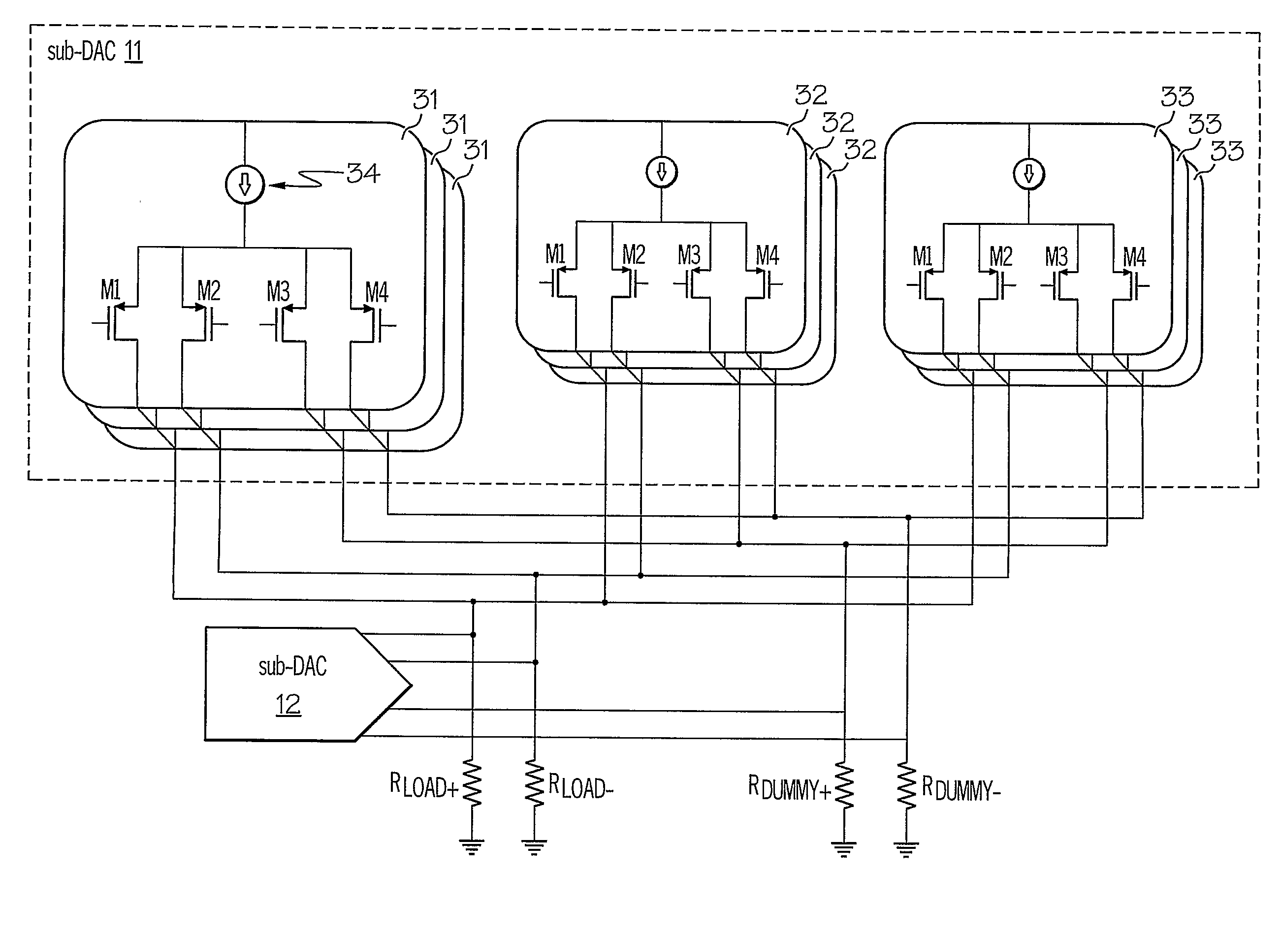
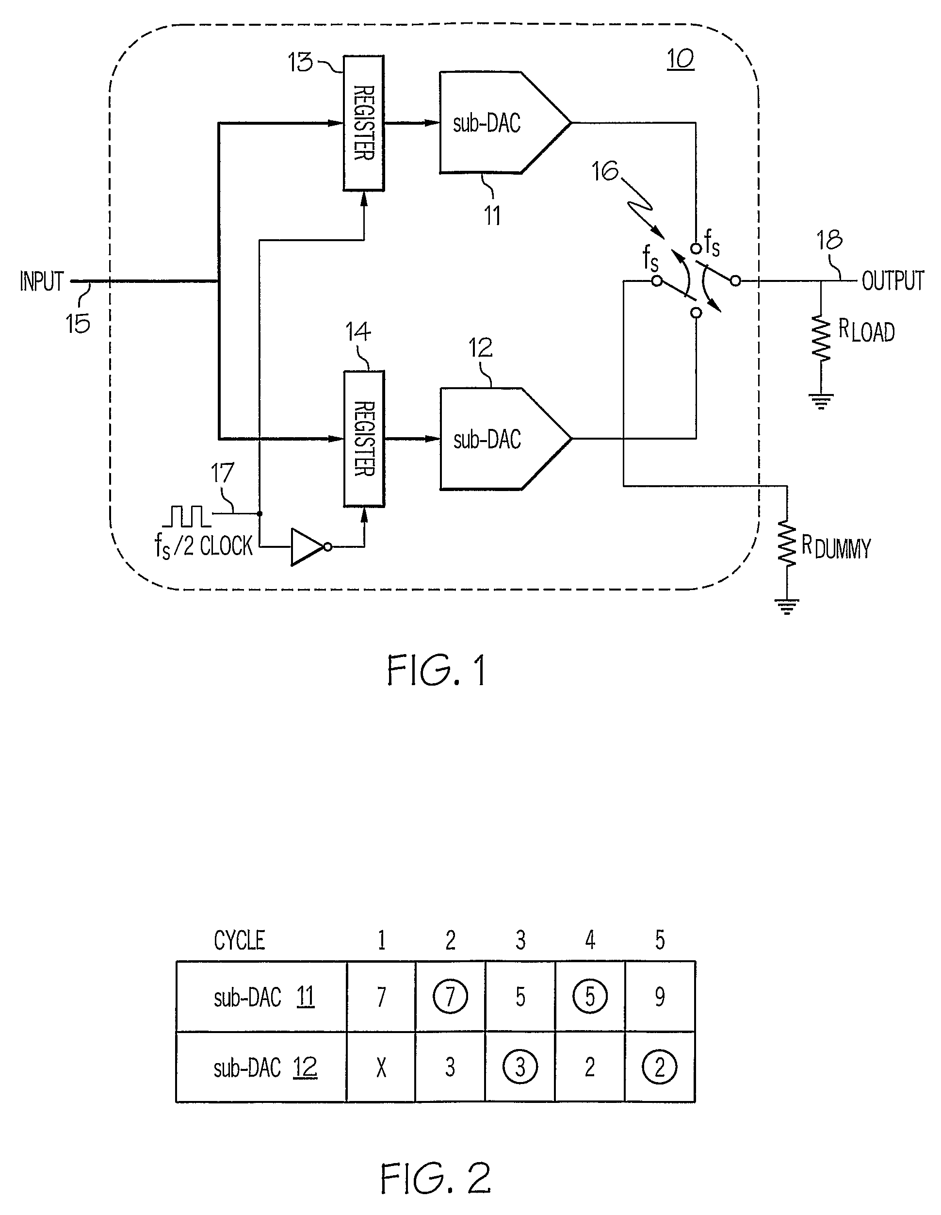
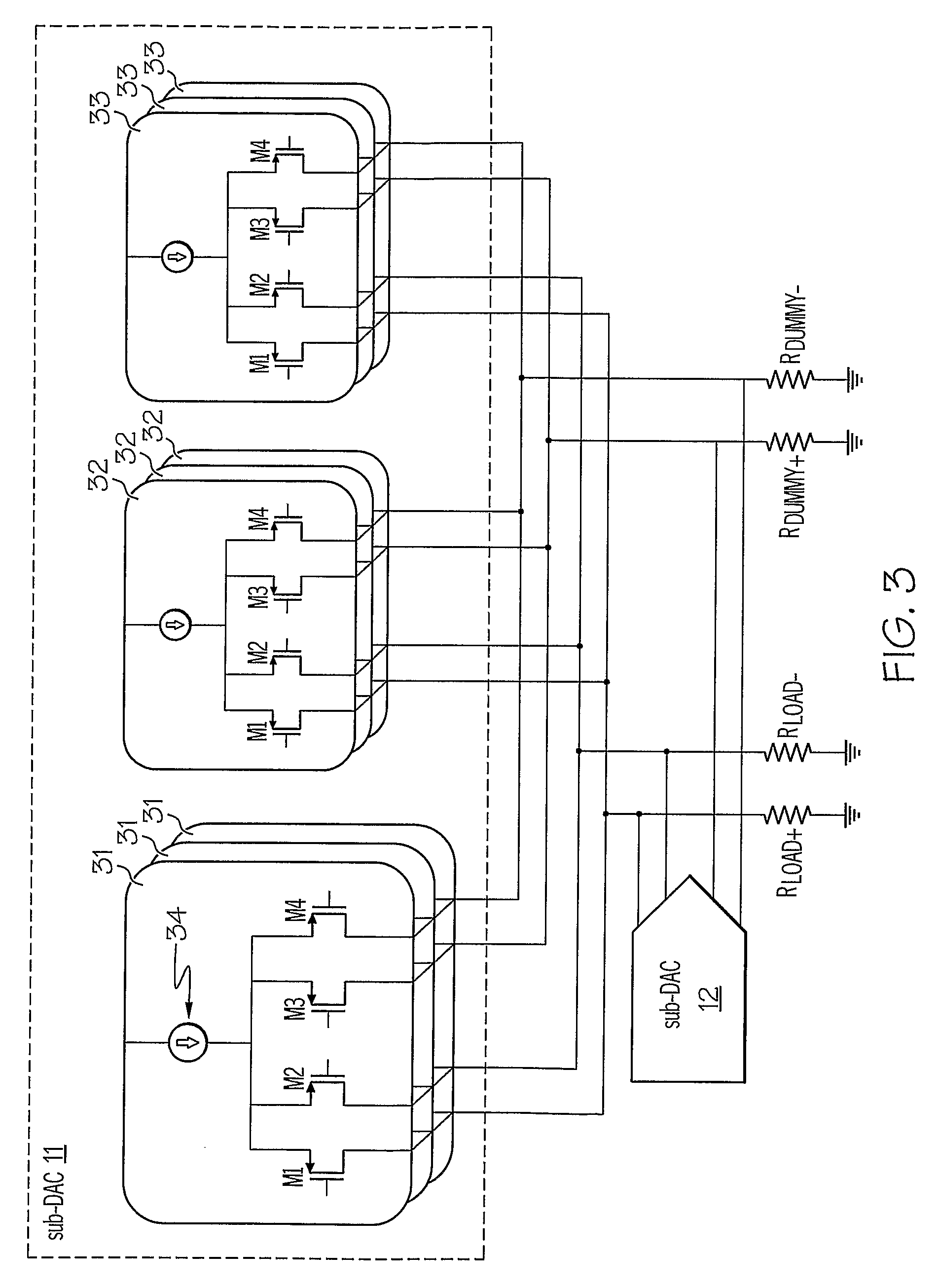
[0016]Referring now to the drawings and in particular to FIG. 1, there is depicted a block diagram of a digital-to-analog converter (DAC), in accordance with a preferred embodiment of the present invention. As shown, a DAC 10 includes a sub-DAC 11 and a sub-DAC 12 connected in parallel. Preferably, both sub-DAC 11 and sub-DAC 12 are current-steering type DACs that are substantially identical to each other. The inputs of sub-DAC 11 and sub-DAC 12 are coupled to an input 15 via a register 13 and a register 14, respectively, that latch data values from input 15. At the rising or falling edge of a clock signal 17 that feeds register 13 and 14, data values from input 15 are stored into, and transferred to the outputs of registers 13 and 14, respectively. The output of sub-DAC 11 and the output of sub-DAC 12 can be selectively connected to a load resistor Rload or a dummy load resistor Rdummy via a switch 16.

[0017]For the sake of simplicity, only one switch 16 is depicted in FIG. 1 for th...


PUM


Abstract

A current-steering type digital-to-analog converter (DAC) is disclosed. The DAC includes a first sub-DAC, a second sub-DAC and a controlling device. Both the first sub-DAC and the second sub-DAC are configured to receive input signals. The controlling device selectively and periodically sends output signals of either the first sub-DAC or the second sub-DAC to a resistive load while sending output signals of the remaining one of the two sub-DACs to a dummy resistive load. An output of the DAC is provided at the resistive load.

Description

RELATED PATENT APPLICATION[0001]The present patent application claims priority to copending provisional application U.S. Ser. No. 60 / 707,702, filed on Aug. 12, 2005.BACKGROUND OF THE INVENTION[0002]1. Technical Field[0003]The present invention relates to mixed-signal circuits in general, and in particular to digital-to-analog converters. Still more particularly, the present invention relates to a current-steering type digital-to-analog converter.[0004]2. Description of Related Art[0005]Digital-to-analog converters (DACs) are electronic circuits for converting signals from a digital domain, where signals are typically represented by discrete quantities, to an analog domain, where signals are typically represented by continuous quantities. Well-known DAC types include resistor-string, charge-redistribution, and current-steering.[0006]Any of the above-mentioned DAC types may use a binary-weighted design, a thermometer-code design, or a combination of both designs to convert a digital s...

Claims


Application Information

Patent Timeline
Patent Type & Authority Patents(United States)
IPC IPC(8): H03M1/66
CPCH03M1/0678H03M1/0697H03M1/74
Inventor TSANG, ROBIN M.
Owner BOARD OF RGT THE UNIV OF TEXAS SYST
Learn More