
Optical power monitor for PON telecommunication

a technology of optical power monitor and pon, applied in the field of optical monitor, can solve the problem of inability to evaluate an intermediate value during such a period, and achieve the effect of high-accuracy monitoring of optical power

Inactive Publication Date: 2010-03-09
FUJITSU LTD
View PDF4 Cites 9 Cited by
  • Summary
  • Abstract
  • Description
  • Claims
  • Application Information

AI Technical Summary

Benefits of technology

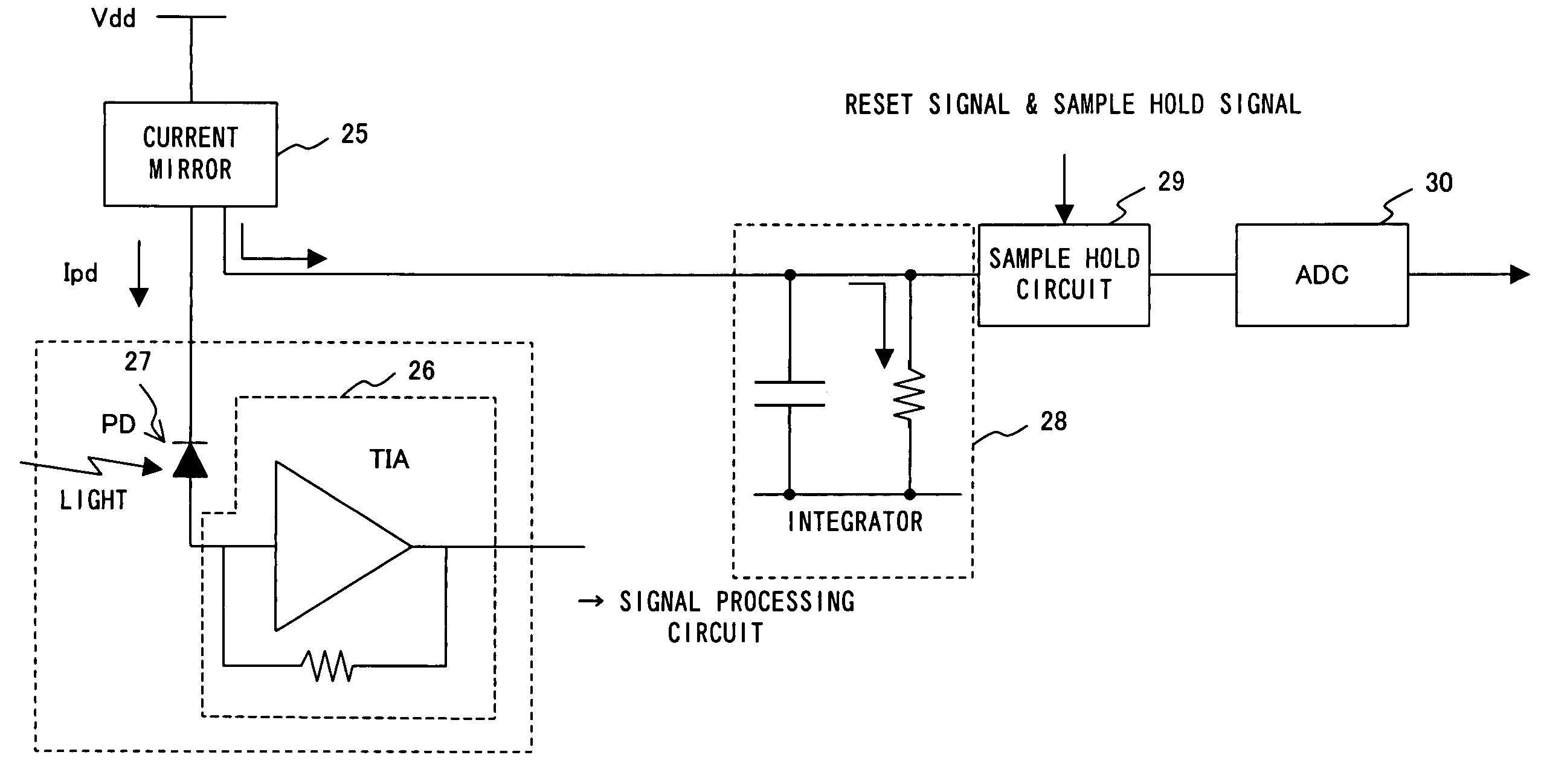
The present invention provides an optical power monitor for use in an optical telecommunication system. The monitor can accurately measure the optical power of each packet, and can obtain information about the path connecting each client to the OLT in real-time. This allows for better monitoring and control of the optical power in the system.

Problems solved by technology

However, if long bits of the same sign are included in a data part of an optical packet, the average optical power is biased toward an optical power of the “0” or “1”, hence making impossible to evaluate an intermediate value during such a period.

Method used


Image

  • Optical power monitor for PON telecommunication
  • Optical power monitor for PON telecommunication
  • Optical power monitor for PON telecommunication

Examples


Embodiment Construction

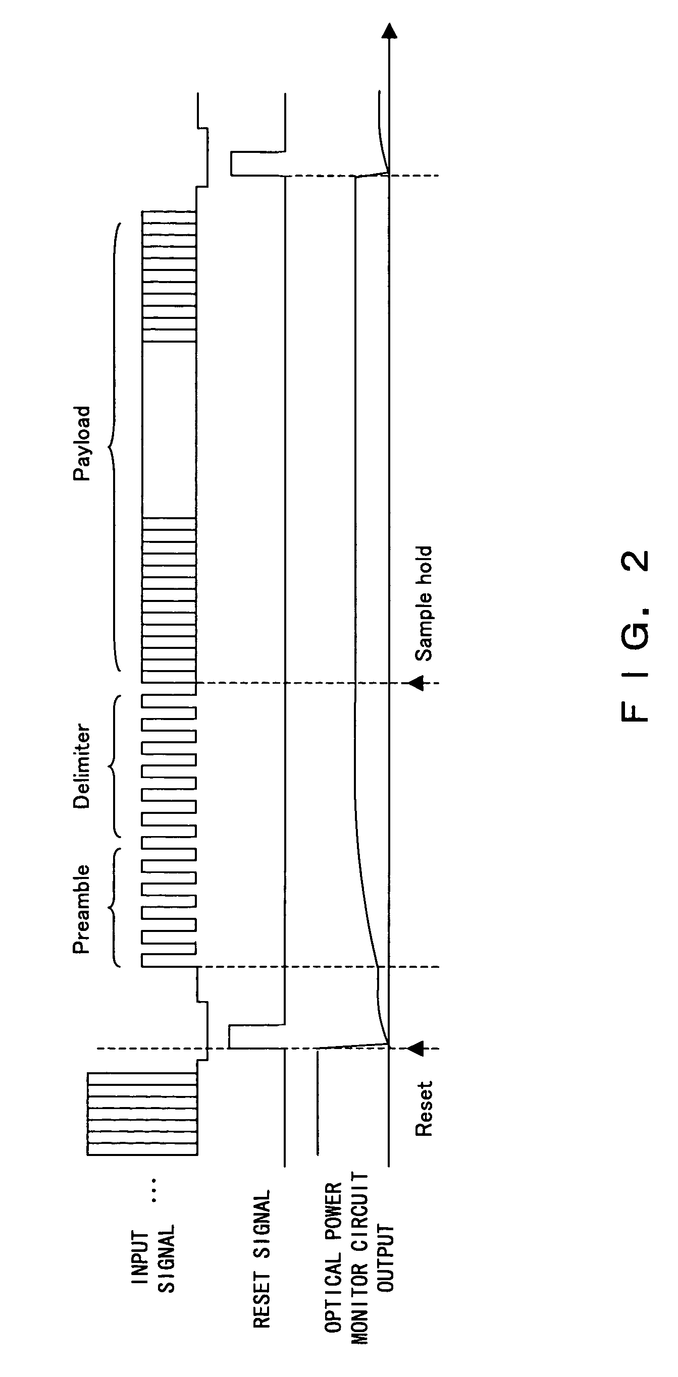
[0021]FIG. 2 is a diagram describing an embodiment of the present invention.

[0022]The header part of a packet includes a time zone of a fixed length called “preamble” and “delimiter” in which “1” and “0” signs appear approximately equally. The “preamble” is a field for synchronizing data (i.e., adjusting a threshold so as to enable a correct detection of the signal values “1 / 0”) and extracting a clock, while the “delimiter” is a field indicating a start of a frame in the head of a packet. The delimiter is followed by a payload part in which the appearance of “1 / 0” signs depends on a data content. And a measurement of an average optical power across the field obtains a measurement value of an approximate intermediate value between “1” and “0” of an optical packet signal in the field, such as preamble and delimiter, in which “1 / 0” signs appear approximately equally. Accordingly, a monitoring of an optical power only within the time period of the header part comprising the preamble and...


PUM


Abstract

In an optical telecommunication system in which an intensity of an arriving optical signal is different for each packet, detected is an optical intensity for each packet with little error. For this purpose, contrived is to detect an average optical intensity across header parts for each packet by focusing on the fact that the header part comprising the preamble and delimiter of a packet is in a bit pattern which includes approximately the same numbers of “0” and “1”.

Description

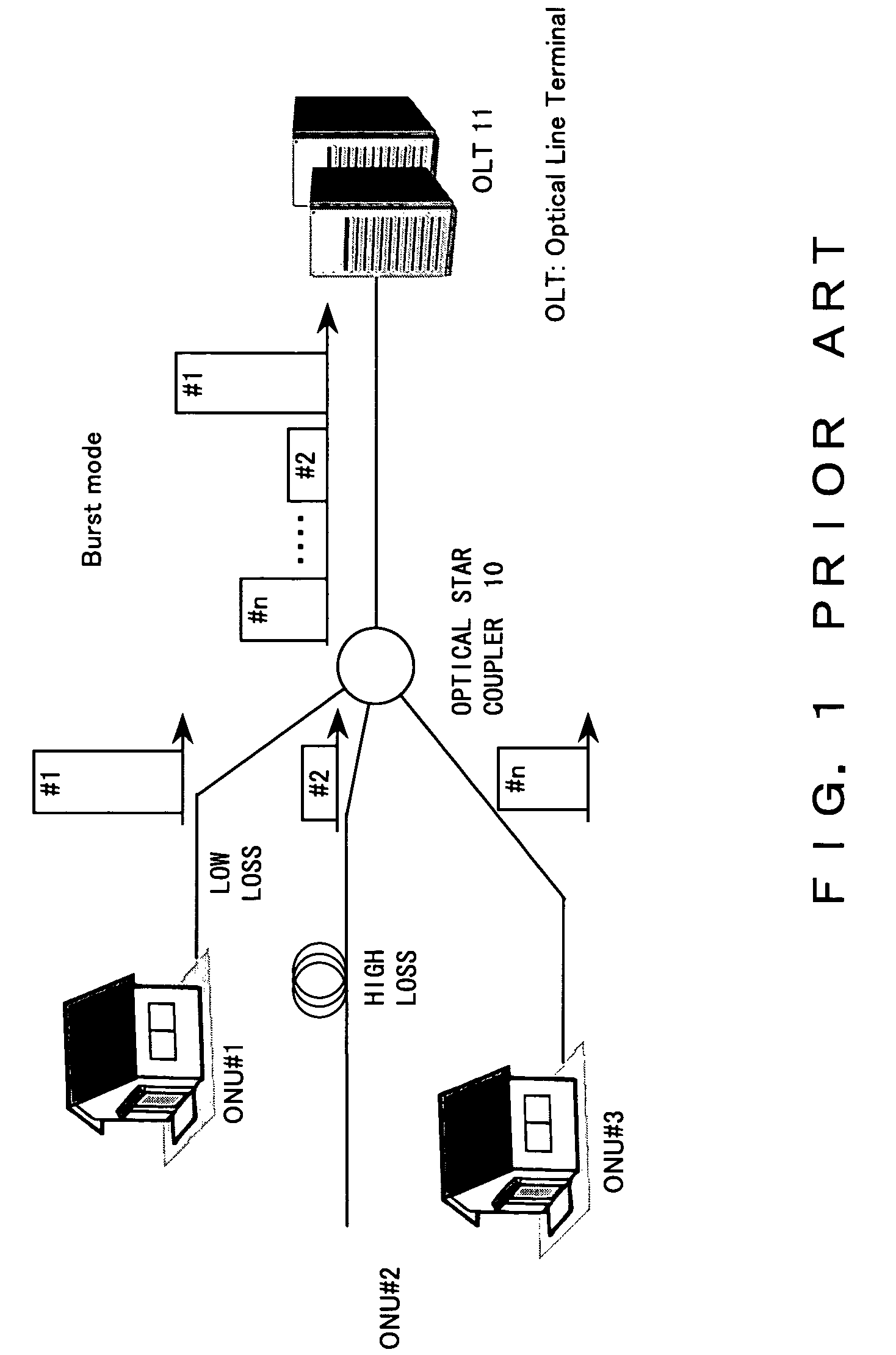
BACKGROUND OF THE INVENTION[0001]1. Field of the Invention[0002]The present invention relates to an optical monitor for use in a reception unit of an optical line terminal (OLT) in a high speed passive optical network (PON).[0003]2. Description of the Related Art[0004]FIG. 1 is a diagram describing a PON telecommunication system.[0005]The PON telecommunication system is one in which an optical star coupler 10 receives an optical signal from each of clients ONU #1 through #3 and transmits it to an OLT 11. An optical signal from each of the clients ONU#1 through #3 is in a packet form. Only the optical star coupler 10 is installed between the clients ONU#1 through #3 and the OLT 11, and an active apparatus such as an optical amplifier is not installed. The individual clients ONU#1 through #3 send out optical packet signals at timings determined between themselves and the OLT 11.[0006]Here, an optical packet signal sent from each of the clients ONU#1 through #3 is input to the optical ...

Claims


Application Information

Patent Timeline
Patent Type & Authority Patents(United States)
IPC IPC(8): H04B10/08H04B10/079H04B10/07H04B10/27H04B10/272H04L12/44
CPCH04B10/07955H04B10/69
Inventor YAMABANA, TETSUJIMORI, KAZUYUKIIDE, SATOSHI
Owner FUJITSU LTD
Learn More