
Separation apparatus and method

a separation apparatus and separation technology, applied in the field of separation apparatus and method, can solve the problem of limited diffraction of photolithography, and achieve the effect of reliable solution

Active Publication Date: 2010-03-02
OBDUCAT AB SE
View PDF9 Cites 12 Cited by
  • Summary
  • Abstract
  • Description
  • Claims
  • Application Information

AI Technical Summary

Benefits of technology

"The invention provides a reliable solution for separating objects attached to each other in a sandwich structure. An apparatus is used to separate the two objects, comprising a support structure, first fastening means, second fastening means, and a pulling force mechanism. The apparatus can also include a positioning mechanism for positioning the sandwich structure and a cutting mechanism for inserting a cutting edge between the objects. The invention also provides a method for separating the two objects by gripping them and using a pulling force at an angle to displace the fastening means away from each other. The technical effects of the invention include improved efficiency and reliability in separating sandwich structures."

Problems solved by technology

For fine scale replication, photolithography is limited by diffraction, which is dependent on the wavelength of the radiation used.

Method used


Image

  • Separation apparatus and method
  • Separation apparatus and method
  • Separation apparatus and method

Examples


Embodiment Construction

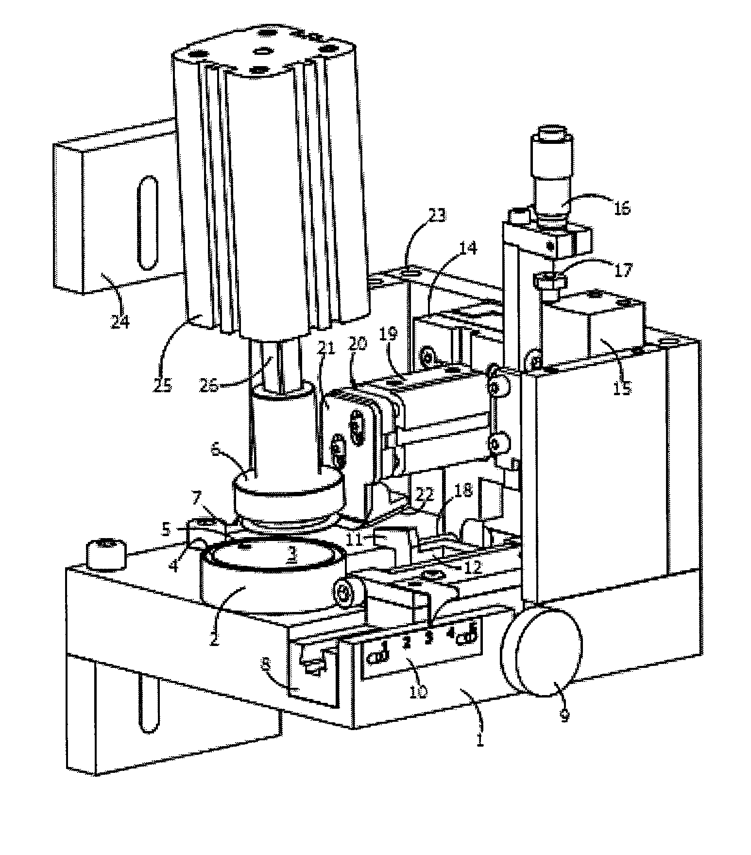
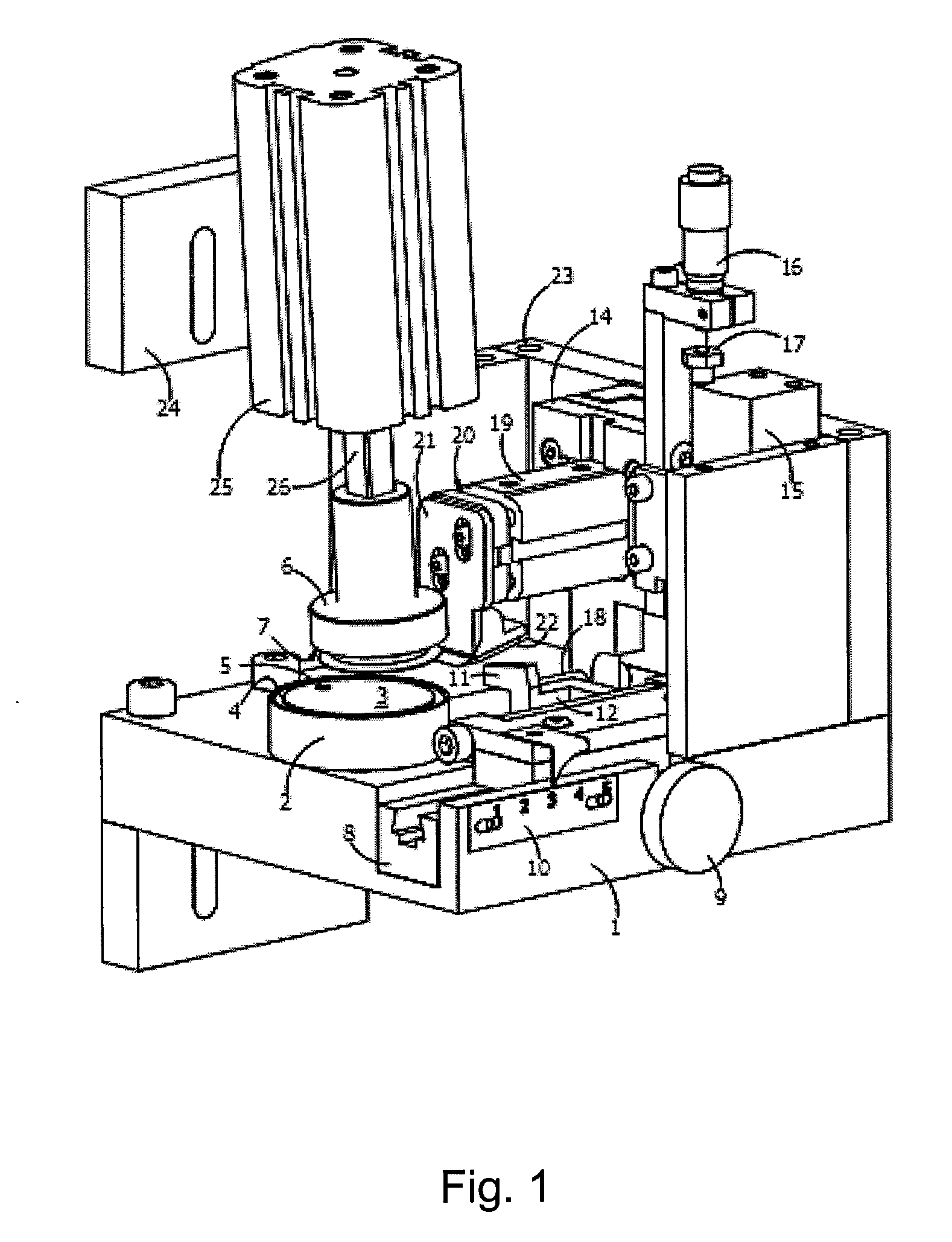
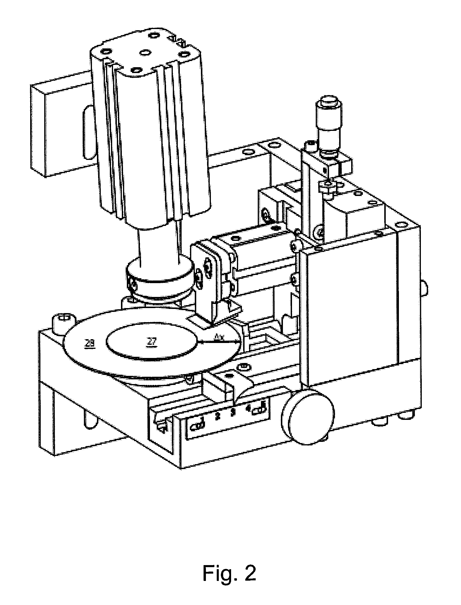
[0039]FIG. 1 illustrates an embodiment of the separation apparatus according to the invention. The apparatus comprises a chassis or support structure 1, to which first fastening means 2 are connected. First fastening means 2 comprises a horizontal first base surface 3, a sealing recess 4 into which an o-ring (not shown) is devised to be received, and an aperture 5 formed in the first base surface on the inner side of the sealing recess 4. A gas pressure supply system (not shown) is connected to aperture 5, for providing an under pressure compared to ambient pressure, herein referred to as vacuum. The base first surface 3 with its o-ring will support and hold a flat object thereto. Opposing the first fastening means 2 are second fastening means 6, comprising a second base surface 7. Similar to the first fastening means 2, a seal (not shown) is applied onto second base surface, forming an engagement rim. However, as will be described more detailed later, the seal provided at second fa...


PUM

PropertyMeasurementUnit
wavelengthaaaaaaaaaa
angleaaaaaaaaaa
angleaaaaaaaaaa

Abstract

An apparatus and method are provided for separating two objects attached to each other in a sandwich structure, such as a stamp and a substrate pressed together in an imprint process. The apparatus includes a support structure, carrying first fastening means having a base surface and first gripping means for supporting and holding a first object, second fastening means, positioned opposite to the first fastening means, having second gripping means for holding a second object, and a pulling force mechanism to provide a pulling force at an angle to the normal direction of the base surface for displacing the two fastening means away from each other. Preferably, the second object is gripped at a periphery portion, and the pulling force is angled inwardly from said periphery portion.

Description

CROSS REFERENCE TO RELATED APPLICATIONS[0001]This application claims the benefit of U.S. Provisional Application No. 60 / 595,123, filed Jun. 8, 2005, and claims the right to priority based on European Application No. 05104935.1, filed Jun. 7, 2005, the content of each of which is incorporated herein by reference in its entirety.FIELD OF THE INVENTION[0002]The present invention relates to means for separating objects attached to each other in a sandwich structure. The invention is particularly suitable for separating a stamp from a substrate, which have been attached to each other at facing surfaces with an intermediate layer of a resist material in a lithographic process, such as an imprint process.BACKGROUND[0003]The trend in microelectronics, as well as in micromechanics, is towards ever smaller dimensions. Some of the most interesting techniques for fabrication of micro and sub micro structures include different types of lithography.[0004]Photolithography typically involves the st...

Claims


Application Information

Patent Timeline
Patent Type & Authority Patents(United States)
IPC IPC(8): B32B38/10
CPCB08B9/035B29C37/0014B29C43/003B29C43/50B82Y10/00B82Y40/00G03F7/0002B29C2043/025B29C2043/5046Y10T156/1168B29C2043/5069Y10T156/1132Y10T156/1944B29C2043/5061
Inventor HEIDARI, BABAKHABENICHT, MATTIAS
Owner OBDUCAT AB SE
Learn More