Triangular-pyramidal cube-corner retroreflective article having curved reflective lateral face
a retroreflective article and triangular pyramidal cube technology, applied in the direction of roads, instruments, traffic signals, etc., can solve the problems of weak observed reflected light, exponentially deteriorating retroreflective efficiency
- Summary
- Abstract
- Description
- Claims
- Application Information
AI Technical Summary
Benefits of technology
Problems solved by technology
Method used
Image
Examples
first embodiment
[0090]A method for forming a retroreflective article of the present invention is more minutely described below by referring to the accompanying drawings.
[0091]FIG. 9 shows a method for forming a V-shaped groove for forming many triangular-pyramidal cube-corner retroreflective element pairs in accordance with a conventionally-known method. FIG. 9(a) shows an illustration in which a horizontally-symmetric V-shaped groove is formed. A one-side groove angle (GL or GR in FIG. 7(b)) shown on the cross section of a formed V-shaped groove shows a constant angle in one V-shaped groove.
[0092]FIG. 9(b) shows an illustration in which a horizontally-asymmetric V-shaped groove is formed. The one-side groove angle (GL or GR in FIG. 7(b)) shown on the cross section of a formed V-shaped groove also shows a constant angle in one V-shaped groove.
[0093]FIG. 9(c) shows an illustration in which a groove whose cross section has a curved shape is shown. The one-side groove angle (GL or GR in FIG. 7(c)) sho...
second embodiment
[0155]A method for forming the retroreflective article of second embodiment of the present invention is described below in detail by referring to the accompanying drawings.
[0156]FIG. 17 shows a method for forming a V-shaped groove used to form a retroreflective article formed of many triangular-pyramidal cube-corner retroreflective element pairs characterized in that a base line constituting any-directional V-shaped groove in second embodiment of the present invention is a nonlinear base line which does not form a linear trajectory and a reflective lateral face formed of the V-shaped groove forms a curved and / or multiple surface.
[0157]FIG. 17(a) shows a V-shaped groove in which a reflective lateral face forms a curved and / or multiple surface even if a one-side groove angle (GLx, GRx, GLy, GRy, GLz, or GRz) is a constant angle in the V-shaped groove because a base line constituting the V-shaped groove has a nonlinear trajectory which does not form a linear trajectory in the horizonta...
example 1
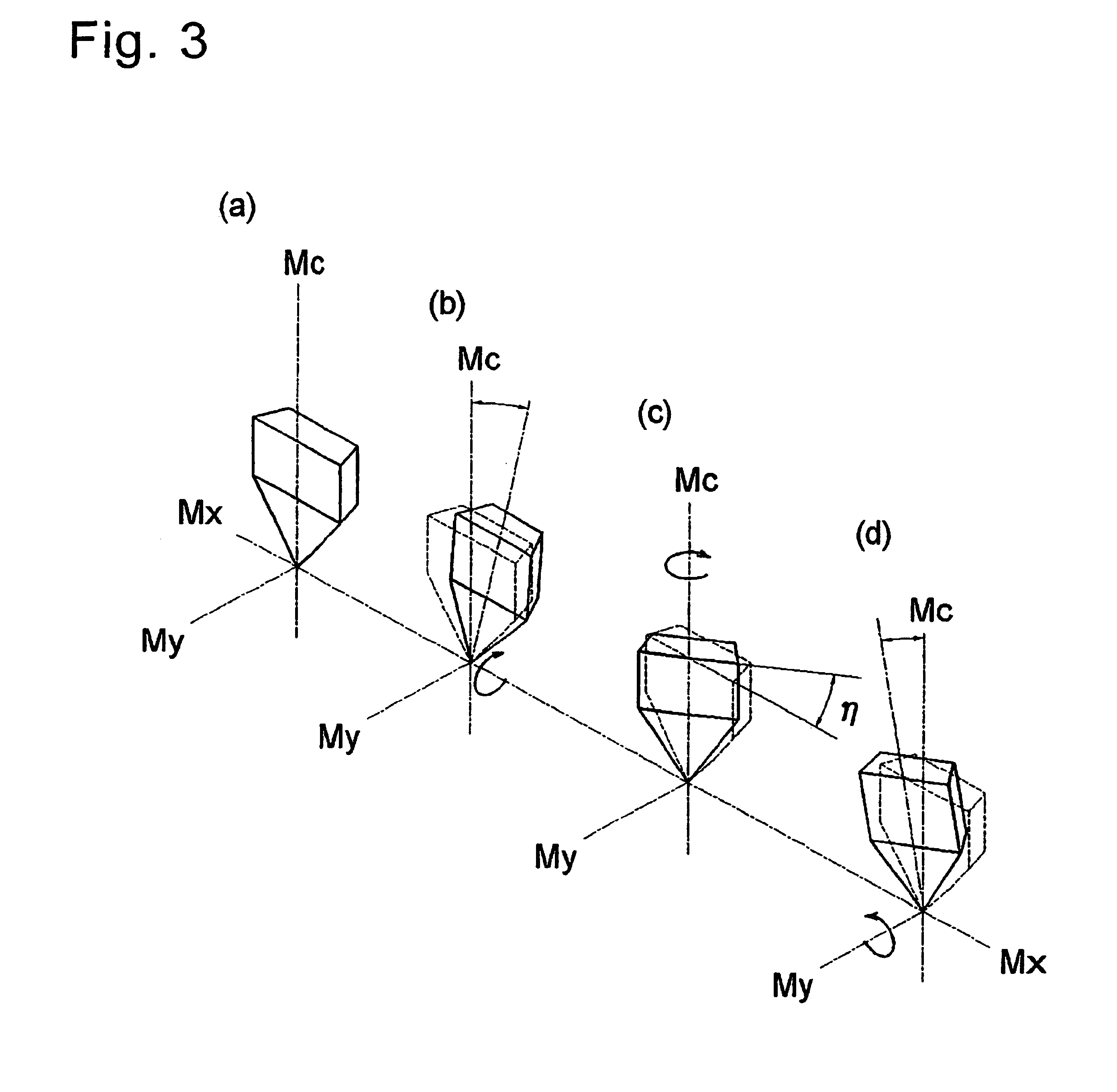
[0200]A die is prepared which has the shape of a retroreflective article of the present invention having a reflective lateral face with the continuous change shown in FIG. 12 so that one-side groove angles at the both sides of three-directional V-shaped grooves of a conventionally-known triangular-pyramidal cube-corner element having the shape shown as Example 1 in Table 1 becomes smaller than a normal one-side groove angle by the maximum degree of 0.01°. In this case, cosine angles (η) of a cutting tool at points A and O are 0°, the slewing angle (η) of the cutting tool at the middle point between the points A and O is 1.55°, and the cosine angle between 0 and 1.55° is continuously changed. The shape of a prepared element has a height (h) of 100 μm and the tilt angle of 0° of a pseudo optical axis. A die having this shape is molded into a nickel die base material in accordance with the fly cutting method and prepared a retroreflective article as Article 1 of the present invention t...
PUM
| Property | Measurement | Unit |
|---|---|---|
| constant angle | aaaaa | aaaaa |
| internal angle | aaaaa | aaaaa |
| internal angle | aaaaa | aaaaa |
Abstract
Description
Claims
Application Information
 - R&D
- Intellectual Property
- Life Sciences
- Materials
- Tech Scout
- Unparalleled Data Quality
- Higher Quality Content
- 60% Fewer Hallucinations
Browse by: Latest US Patents, China's latest patents, Technical Efficacy Thesaurus, Application Domain, Technology Topic, Popular Technical Reports.
© 2025 PatSnap. All rights reserved.Legal|Privacy policy|Modern Slavery Act Transparency Statement|Sitemap|About US| Contact US: help@patsnap.com


