
Triangular-pyramidal cube-corner retroreflective article having curved reflective lateral face

a retroreflective article and triangular pyramidal cube technology, applied in the direction of roads, instruments, traffic signals, etc., can solve the problems of weak observed reflected light, exponentially deteriorating retroreflective efficiency

Inactive Publication Date: 2010-07-01
NIPPON CARBIDE KOGYO KK
View PDF17 Cites 9 Cited by
  • Summary
  • Abstract
  • Description
  • Claims
  • Application Information

AI Technical Summary

Benefits of technology

This design enhances retroreflective performance by uniformly distributing retroreflected light across various observation angles, improving both observation and incident angularity, and allowing for selective directionality of light spread, particularly beneficial for applications like traffic signs and vehicle safety markers.

Problems solved by technology

However, there is a disadvantage that the retroreflective efficiency is exponentially deteriorated as the angle increases.
Moreover, there is a disadvantage that when an observer observes retroreflective light at a position separate from a light source, observed reflected light is weak.
Because of the above reasons, the conventionally-known triangular-pyramidal retroreflective element has a disadvantage that the retroreflective efficiency is exponentially deteriorated as the angle formed between a line vertical to the reference surface of a retroreflective article and incoming ray or an incident angle increases.
Thereby, a retroreflective article using a triangular-pyramidal reflective element is inferior in retroreflective characteristic at a large incoming angle even if it is generally superior in retroreflective characteristic in the front direction and has a disadvantage that it is inferior in the so-called incident angularity.
Moreover, because the shape of the element is triangular, the element has a disadvantage that the retroreflective efficiency is greatly changed depending on a direction of the element from which light is incoming or a direction in which an observer is located (rotation angle).
However, divergence of reflected light having an extremely narrow retroreflective light easily causes a practical disadvantage that when the light emitted from the head lamp of a vehicle is retroreflected from a traffic sign, retroreflective light is concentrically returned to the head lamp and it does not easily reach eyes of a driver who is present at a position separate from its incident-light axis.
This disadvantage is particularly remarkable because an angle (observation angle) formed between the incident-light axis of a ray and an axis connecting a driver and a reflective point (observation axis) increases.
Thus, a retroreflective article using a conventionally-known triangular-pyramidal retroreflective element has a disadvantage that it is inferior in observation angularity.
However, the above US patent of Jungersen does not specifically disclose a very-small triangular-pyramidal reflective element to be described later in order to provide superior observation angularity or incident angularity.
The US patent of Stamm improves the problem of deterioration of retroreflective efficiency and the disadvantage that retroreflection does not occur because the light incoming at an angle of less than internal total-reflective condition passes through the interface of the element by vacuum-evaporating the reflective lateral face of a reflective element by, for example, metal such as aluminum, mirror-reflecting incoming light, and increasing an incident angle.
Therefore, disadvantage that the reflection performance is deteriorated easily occurs because the appearances of an obtained retroreflective sheeting and retroreflective article become dark or metal such as aluminum or silver used for a mirror-layer is oxidized due to entrance of water or air during use.
However, in the case of these inventions, observation angularity is not improved though incident angularity is improved.
However, periodically changing angles of adjacent V-shaped grooves increases the difficulty of molding.
Even if the difficulty can be conquered, uniform spread of reflected light cannot be made because combinations of deviations which can be provided are finite.
However, it is very difficult to form a purposed shape by the working tool having the curved-sectional shape.
Therefore, it is very difficult to obtain a quadric surface based on purposed design because of the difficulty of tool working.
Moreover, it is impossible to form various-shaped quadric surfaces decided by only the shape of a working tool to be used on the same retroreflective article.
However, any one of these inventions has a disadvantage that it is difficult to prepare a tool and perform die molding.

Method used


Image

  • Triangular-pyramidal cube-corner retroreflective article having curved reflective lateral face
  • Triangular-pyramidal cube-corner retroreflective article having curved reflective lateral face
  • Triangular-pyramidal cube-corner retroreflective article having curved reflective lateral face

Examples


first embodiment

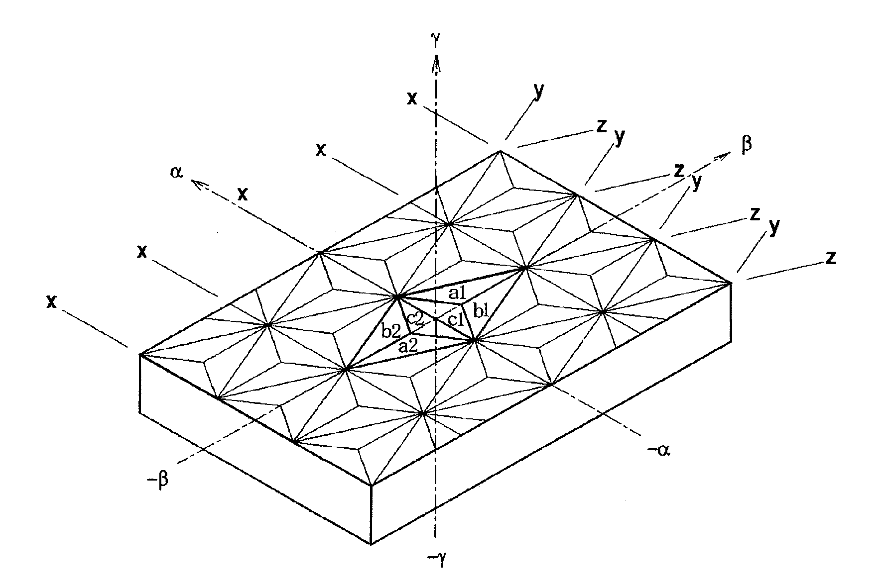
[0092]A method for forming a retroreflective article of the present invention is more minutely described below by referring to the accompanying drawings.

[0093]FIG. 9 shows a method for forming a V-shaped groove for forming many triangular-pyramidal cube-corner retroreflective element pairs in accordance with a conventionally-known method. FIG. 9(a) shows an illustration in which a horizontally-symmetric V-shaped groove is formed. A one-side groove angle (GL or GR in FIG. 7(b)) shown on the cross section of a formed V-shaped groove shows a constant angle in one V-shaped groove.

[0094]FIG. 9(b) shows an illustration in which a horizontally-asymmetric V-shaped groove is formed. The one-side groove angle (GL or GR in FIG. 7(b)) shown on the cross section of a formed V-shaped groove also shows a constant angle in one V-shaped groove.

[0095]FIG. 9(c) shows an illustration in which a groove whose cross section has a curved shape is shown. The one-side groove angle (GL or GR in FIG. 7(c)) sho...

second embodiment

[0156]A Method for Forming the Retroreflective Article of Second embodiment of the present invention is described below in detail by referring to the accompanying drawings.

[0157]FIG. 17 shows a method for forming a V-shaped groove used to form a retroreflective article formed of many triangular-pyramidal cube-corner retroreflective element pairs characterized in that a base line constituting any-directional V-shaped groove in second embodiment of the present invention is a nonlinear base line which does not form a linear trajectory and a reflective lateral face formed of the V-shaped groove forms a curved and / or multiple surface.

[0158]FIG. 17(a) shows a V-shaped groove in which a reflective lateral face forms a curved and / or multiple surface even if a one-side groove angle (GLx, GRx, GLy, GRy, GLz, or GRz) is a constant angle in the V-shaped groove because a base line constituting the V-shaped groove has a nonlinear trajectory which does not form a linear trajectory in the horizonta...

example 1

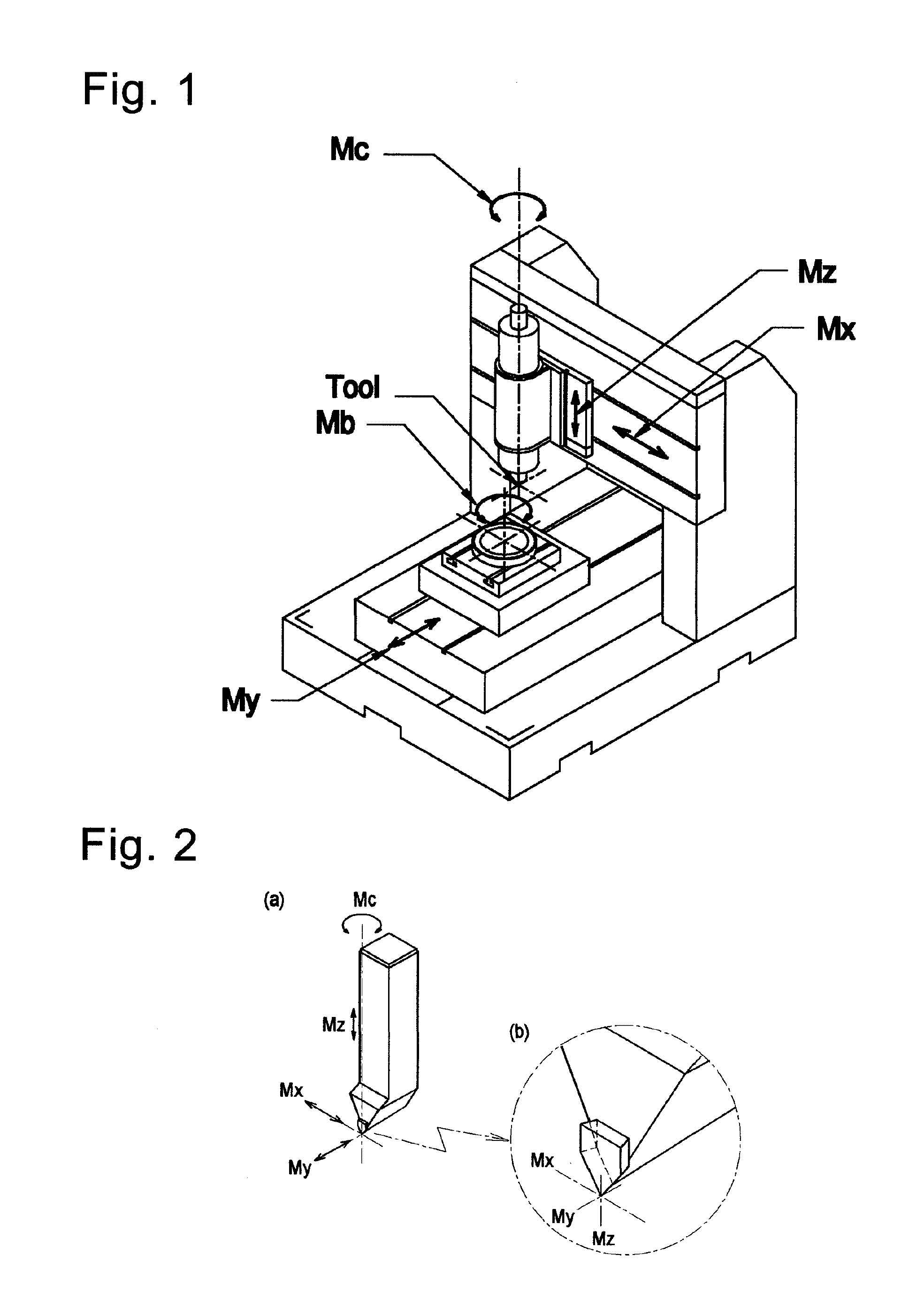
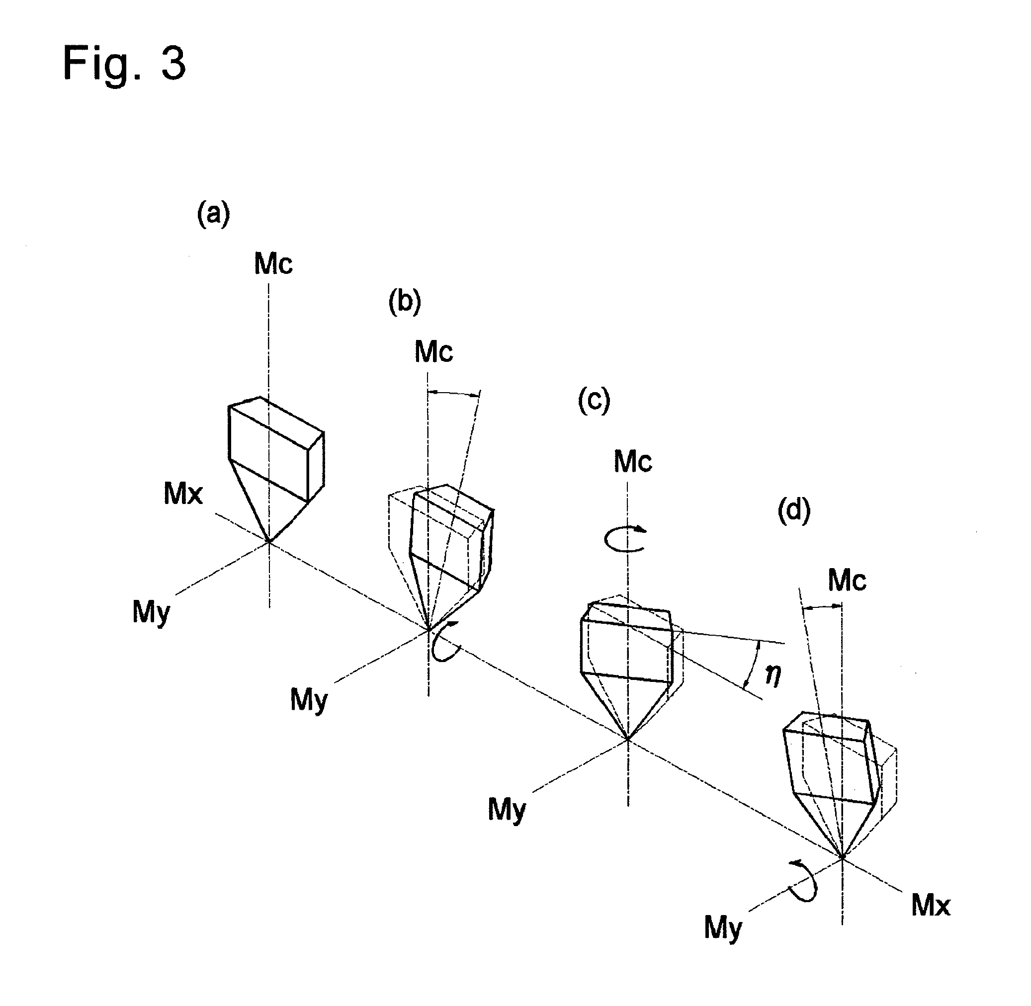
[0200]A die is prepared which has the shape of a retroreflective article of the present invention having a reflective lateral face with the continuous change shown in FIG. 12 so that one-side groove angles at the both sides of three-directional V-shaped grooves of a conventionally-known triangular-pyramidal cube-corner element having the shape shown as Example 1 in Table 1 becomes smaller than a normal one-side groove angle by the maximum degree of 0.01°. In this case, cosine angles (η) of a cutting tool at points A and O are 0°, the slewing angle (η) of the cutting tool at the middle point between the points A and O is 1.55°, and the cosine angle between 0 and 1.55° is continuously changed. The shape of a prepared element has a height (h) of 100 μm and the tilt angle of 0° of a pseudo optical axis. A die having this shape is molded into a nickel die base material in accordance with the fly cutting method and prepared a retroreflective article as Article 1 of the present invention t...


PUM

PropertyMeasurementUnit
tilt angleaaaaaaaaaa
sizeaaaaaaaaaa

Abstract

To provide a retroreflective article formed of many triangular-pyramidal cube-corner retroreflective element pairs. One-side groove angle formed between a cross line between a plane vertical to the common plane and to a V-groove vertical plane which includes the base line of a V-shaped groove is vertical to the common plane, and a reflective lateral face containing the base line of the v-shaped groove, and the V-groove vertical plane, does not form a constant angle in the reflective lateral face but the lateral face forms a curved and / or multiple surface. A base line constituting any directional V-shaped groove in retroreflective element pairs is a nonlinear base line which does not form a linear trajectory and the reflective lateral face formed of the V-shaped groove forms a curved and / or multiple surface.

Description

[0001]This application is a division of application Ser. No. 10 / 581,490 filed Aug. 10, 2006, which in turn is a national stage of PCT Application No. PCT / JP2004 / 018329 filed Dec. 2, 2004.TECHNICAL FIELD[0002]The present invention relates to a retroreflective article such as a triangular-pyramidal cube-corner retroreflective sheeting having a new structure. More particularly, the present invention relates to a retroreflective article such as a cube-corner retroreflective sheeting in which triangular-pyramidal cube-corner reflective elements having a new structure (hereafter referred to as triangular-pyramidal reflective elements or simply referred to as reflective elements) are arranged in a closest-packed state by sharing their base line.[0003]Particularly, the present invention relates to a retroreflective article such as a cube-corner retroreflective sheeting constituted of triangular-pyramidal cube-corner retroreflective elements useful for signs such as a road sign (general traf...

Claims


Application Information

Patent Timeline
Patent Type & Authority Applications(United States)
IPC IPC(8): G02B5/124B29D11/00E01F9/615G02B5/122
CPCB29D11/00605G02B5/124Y10T409/502624Y10T428/2457G02B5/122
Inventor MIMURA, IKUO
Owner NIPPON CARBIDE KOGYO KK
Learn More