
Image sensing apparatus

a technology of image sensing and apparatus, applied in the field of image sensing apparatus, can solve the problems of narrow dynamic range and poor contras

Inactive Publication Date: 2010-02-23
KONICA MINOLTA INC
View PDF7 Cites 27 Cited by
  • Summary
  • Abstract
  • Description
  • Claims
  • Application Information

AI Technical Summary

Benefits of technology

Enables capturing subjects with optimal exposure and dynamic range, securing a desired exposure amount or dynamic range depending on shooting conditions, while maintaining high contrast and wide dynamic range.

Problems solved by technology

However, the image sensor has a demerit that the dynamic range is narrow.
On the other hand, in the log operative state of the image sensor, although a wide dynamic range is secured because the output that has been natural-logarithmically converted according to the amount of incident light is obtained, contrast becomes poor because the image signal is logarithmically compressed.

Method used


Image

  • Image sensing apparatus
  • Image sensing apparatus
  • Image sensing apparatus

Examples


first embodiment

[0166]In the following, the first embodiment of the invention is described referring to FIGS. 1 through 29.

[0167](Description on External Construction of Image Sensing Apparatus)

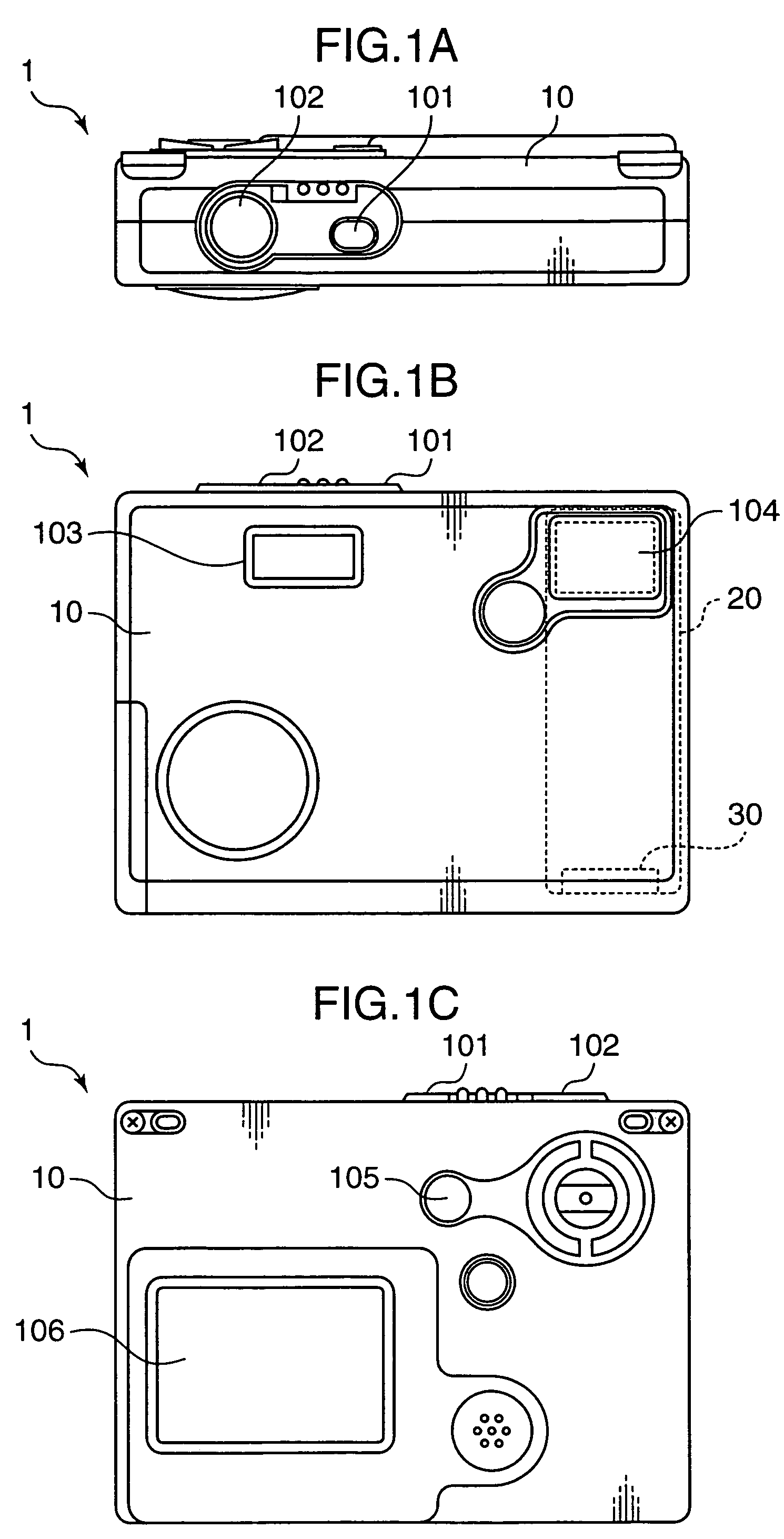
[0168]FIGS. 1A through 1C are diagrams showing external appearance of a compact digital camera 1 to which an image sensing apparatus as the first embodiment is applied, wherein FIG. 1A is a top plan view, FIG. 1B is a front view, and FIG. 1C is a rear view. The digital camera 1, as an example of image sensing apparatuses, has a power supply switch 101 and a release switch 102 on a top part of a camera body 10, a flash section 103 and a taking lens aperture 104 on a front part thereof, and various operation buttons such as a mode setting switch 105, and a LCD section 106 comprised of a liquid crystal display (LCD) monitor on a rear part thereof A retractable lens barrel 20 is provided inside the camera body 10, as well as various parts constituting the camera body 10.

[0169]The power supply switch 101 is a pre...

second embodiment

[0397]Next, the second embodiment is described referring to FIGS. 30 through 36.

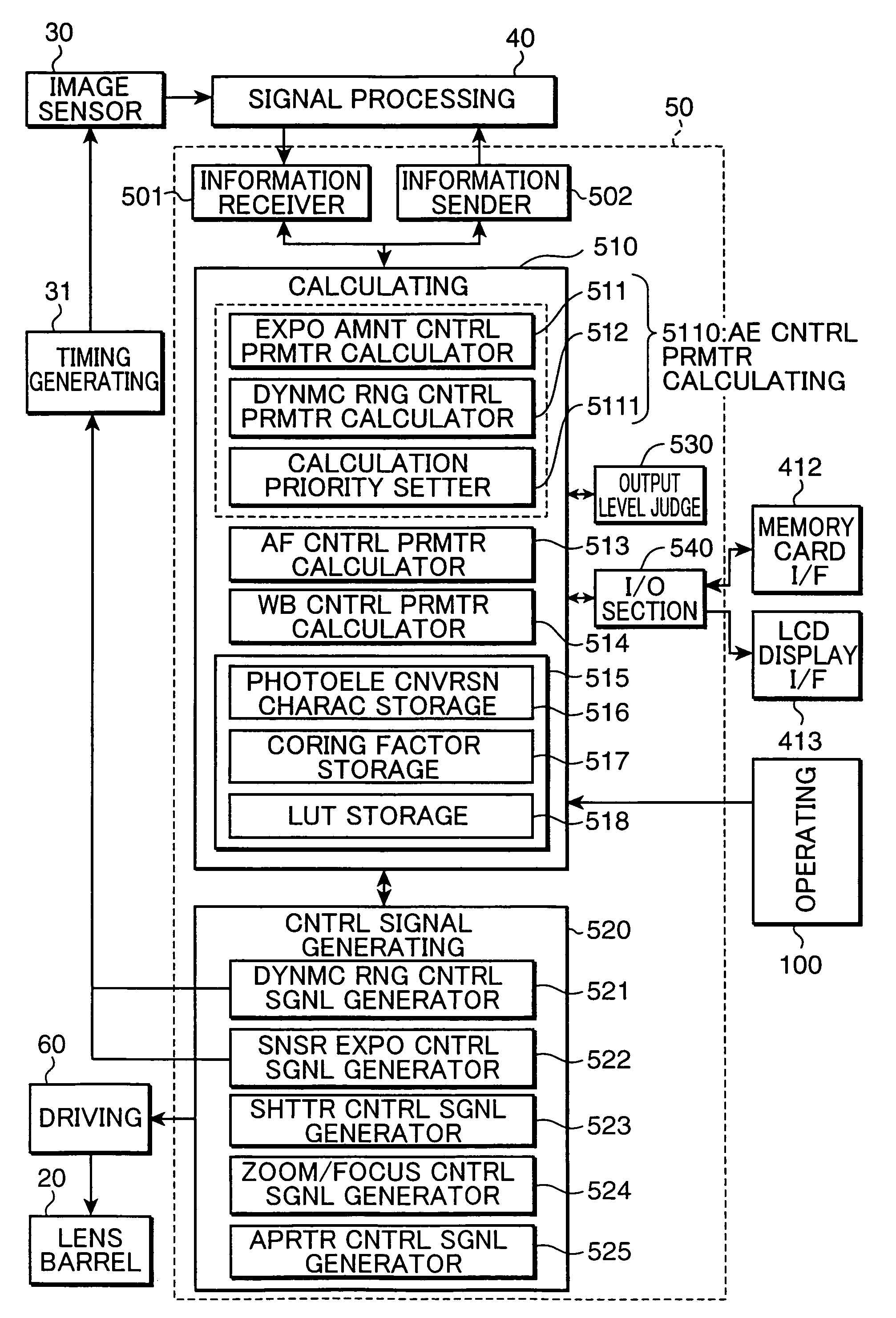
[0398]In the first embodiment, described is the AE control of prioritizing the exposure amount control parameter calculation or the dynamic range control parameter calculation, namely, the exposure amount control or the dynamic range control. In the second embodiment, AE control of securing a predetermined sensor output corresponding to a target subject luminance on a priority basis (hereinafter, this is called as “target level prioritizing system” or “target level prioritizing mode”, which corresponds to the exposure amount control parameter calculation prioritizing mode in the first embodiment), or AE control of securing a dynamic range on a priority basis (hereinafter, this is called as “dynamic range prioritizing system” or “dynamic range prioritizing mode”, which corresponds to the dynamic range control parameter calculation prioritizing mode in the first embodiment) is carried out by performing a f...

third embodiment

[0448]In the following, the third embodiment of the invention is described referring to FIGS. 37 through 52.

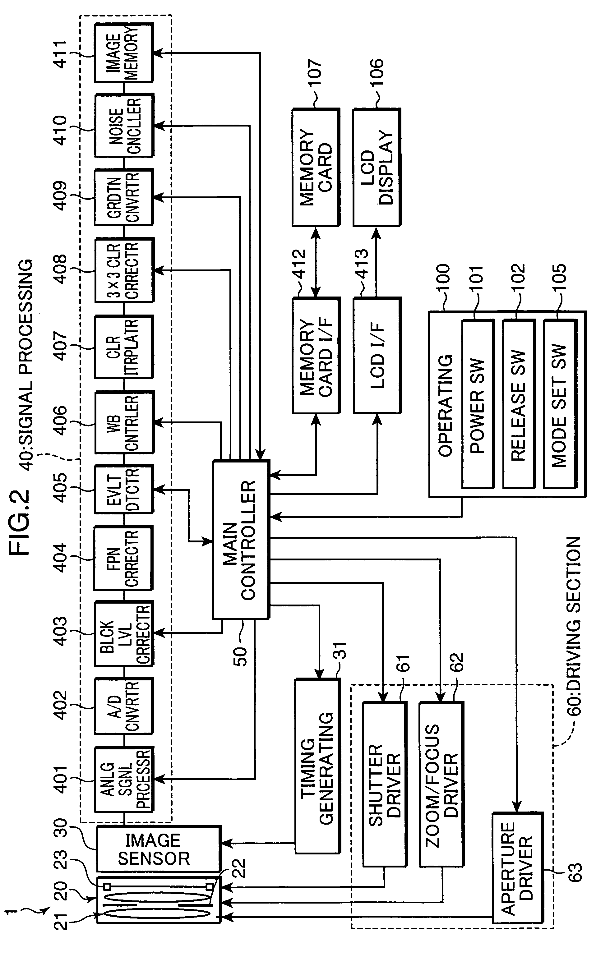
[0449]The third embodiment is different from the first and the second embodiments in the AE controlling method. The AE control in the first embodiment is performed by the exposure amount control as shown in FIG. 18A, and by the dynamic range control as shown in FIG. 18B. The exposure amount control (A) is performed based on control of the exposure time, namely, the integration time of the image sensor 30, or the opening time of the shutter 23, and based on control of the aperture value, namely, the aperture area of the diaphragm 22, and the dynamic range control (B) is performed based on control of the photoelectric conversion characteristic, namely, the position of the inflection point, as summarized below.

[0450](A) Exposure amount control based on exposure time control, i.e., control of the integration time or the shutter opening time, or based on aperture control, i.e., con...


PUM


Abstract

An image sensing apparatus is constructed in such a manner that a calculation priority setter 5111 (5111a) sets a priority between exposure amount control by an exposure amount control parameter calculator 511 (511a) serving as exposure amount controller, and dynamic range control by a dynamic range control parameter calculator 512 (512a) serving as dynamic range controller. Exposure control is executed by performing the exposure amount control and the dynamic range control based on a photoelectric conversion characteristic, by using exposure evaluation values detected by an evaluation value detector 405, based on the priority set by the calculation priority setter 5111 (5111a). This arrangement provides an image sensing apparatus capable of performing exposure control with high latitude, wherein a user is allowed to capture a subject in an optimal exposure state, with an appropriate dynamic range being secured, and control primarily based on the exposure amount control or control primarily based on the dynamic range control is performed on the priority basis.

Description

[0001]This application is based on Japanese Patent Application Nos. 2004-166614, 2004-191993, 2005-77725, and 2005-77825 respectively filed on Jun. 4, 2004, Jun. 29, 2004, Mar. 17, 2005, and Mar. 17, 2005, the contents of which are hereby incorporated by reference.BACKGROUND OF THE INVENTION[0002]1. Field of the Invention[0003]The present invention relates to an image sensing apparatus provided with an image sensor for generating an electrical signal commensurate with the amount of incident light, and particularly relates to an image sensing apparatus using an image sensor having a photoelectric conversion characteristic comprised of two different characteristic areas, as represented by an image sensor which has a photoelectric conversion characteristic comprised of a first area where the electrical signal is outputted after being converted according to a first characteristic in relation to the amount of incident light, and a second area where the electrical signal is outputted afte...

Claims


Application Information

Patent Timeline
Patent Type & Authority Patents(United States)
IPC IPC(8): H04N5/238H04N23/75H04N23/76
CPCH04N5/235H04N5/2351H04N5/2355H04N5/243H04N23/70H04N23/741H04N23/76H04N23/71
Inventor KAMON, KOICHISATO, KAZUCHIKAMINAKUTI, JUN
Owner KONICA MINOLTA INC
Learn More