
Fusible link unit

a technology of a link unit and a sleeve, which is applied in the direction of electrical equipment, basic electric elements, emergency protective devices, etc., can solve the problems of reducing the cross section of the pressed area of the groove, disadvantage, and current-carrying capacity, and achieve the effect of improving quality

Active Publication Date: 2010-02-16
YAZAKI CORP
View PDF25 Cites 33 Cited by
  • Summary
  • Abstract
  • Description
  • Claims
  • Application Information

AI Technical Summary

Benefits of technology

The solution enhances the quality and reliability of the fusible link unit by preventing warping and maintaining current-carrying capacity, allowing for easier and more precise bending without the need for grooves, thus improving the overall performance and safety.

Problems solved by technology

However, a cross section of the pressed area of the groove will decrease, and thus this decrease is disadvantage in view of a current-carrying capacity.

Method used


Image

  • Fusible link unit
  • Fusible link unit
  • Fusible link unit

Examples


Embodiment Construction

[0028]Descriptions will be provided hereinafter for an embodiment of the present invention with reference to the drawings.

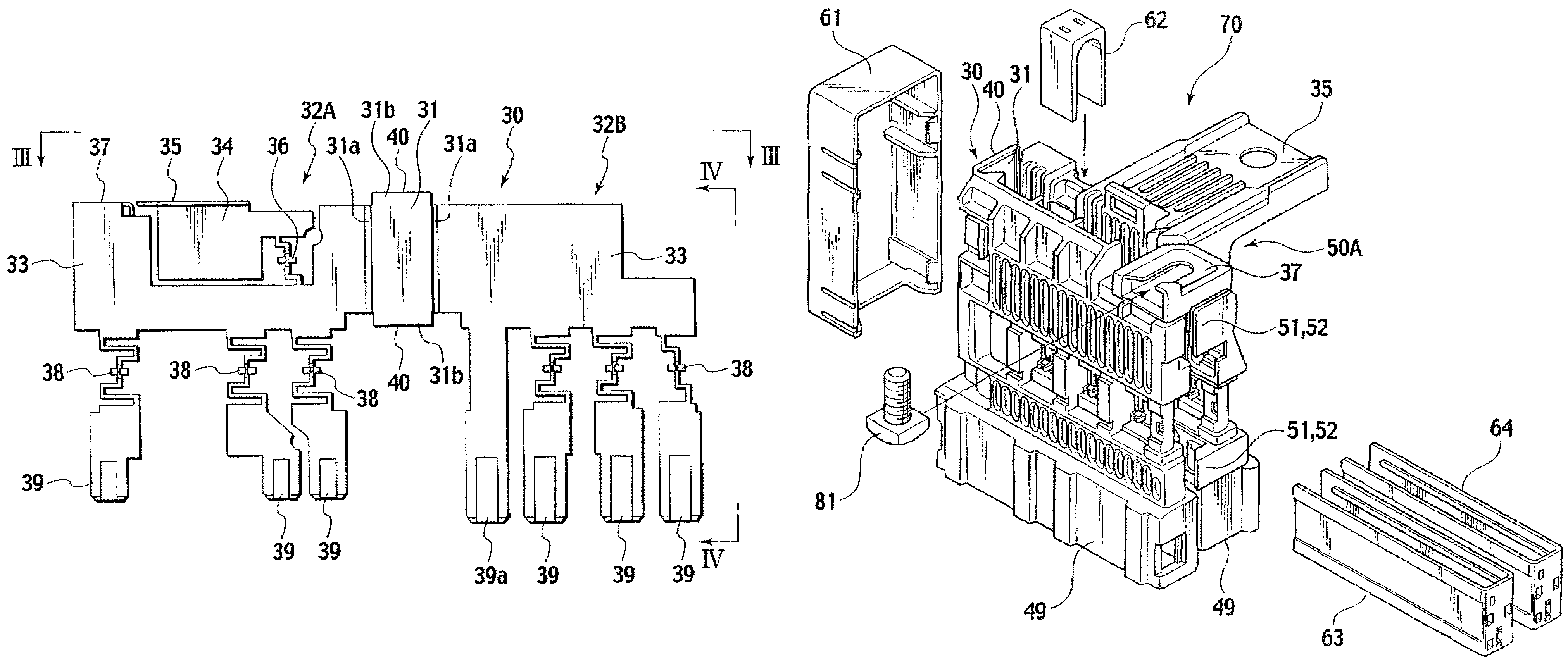
[0029]A fusible link unit 70 shown in FIGS. 2 to 7 includes: a bus bar 30; resin-made housings 42A and 42B fitted respectively to expected portions in the bus bar 30 by insert molding; and resin-made covers 61 to 64 provided to cover exposed portions of the bus bar 30.

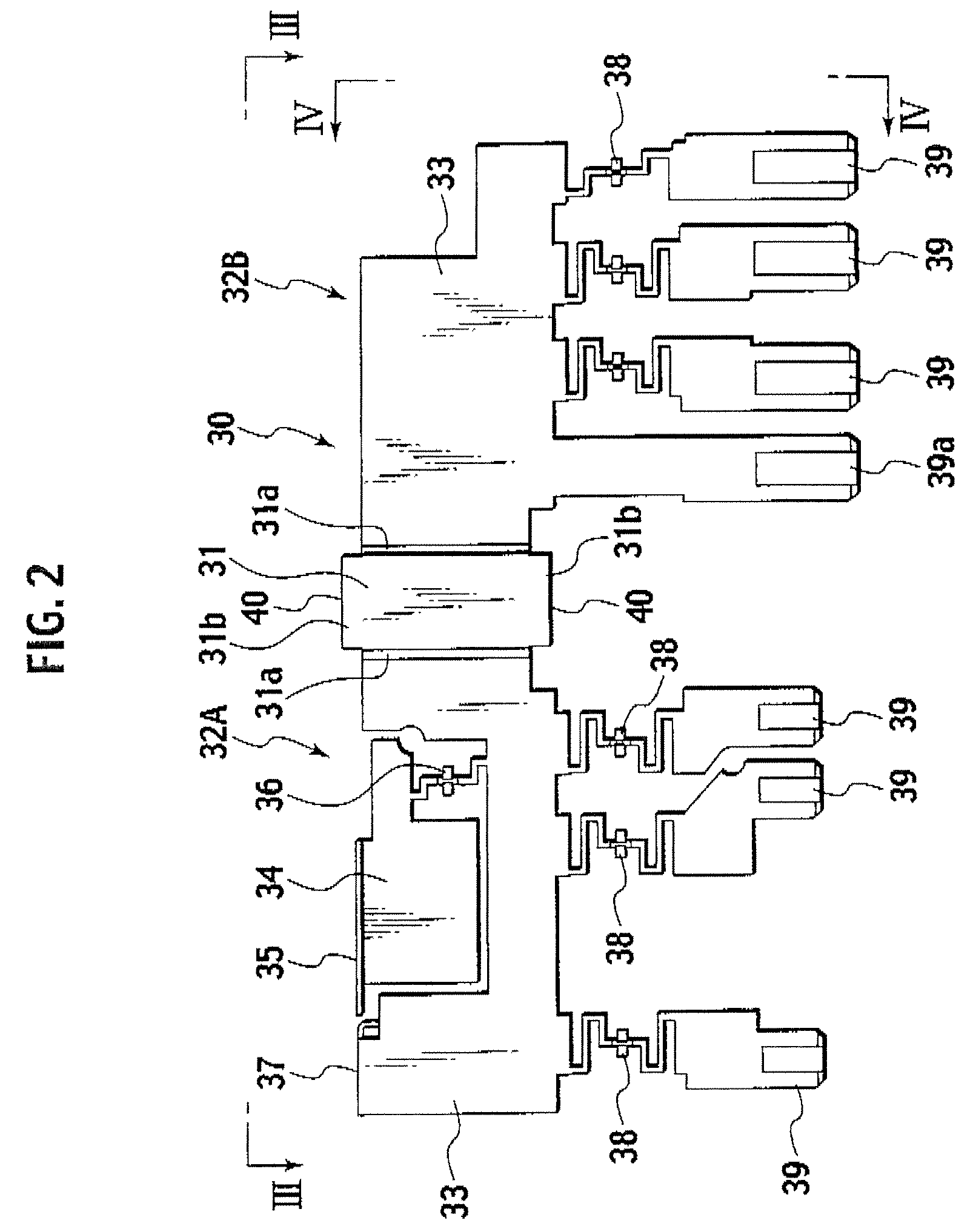
[0030]As shown in FIGS. 2 to 4, the bus bar 30 is formed by press-molding an electrically conductive plate. A band plate portion 31 and two fuse circuit-forming members 32A and 32B are integrally formed on the bus bar 30 by placing the band plate portion 31 in the center, and by forming the two fuse circuit-forming members 32A and 32B contiguously to two sides of the band plate portion 31 and bending the fuse circuit-forming members 32A and 32B along the two respective side ends 31a of the band plate portion 31 in the same direction while arranged side-by-side with a clearance equal to the width of ...


PUM


Abstract

Disclosed is a fusible link unit which is capable of being directly connected to a battery, and which includes: a band plate portion integrally formed in a bus bar; two fuse circuit-forming members contiguously formed respectively to two sides of the band plate portion; and bodies each including an electrically insulating housing formed onto a corresponding one of the fuse circuit-forming members by insert molding. Flanges as long as the entire width of the band plate portion are formed respectively in two end edges of the band plate portion by bending the flanges from the two end edges in the plate thickness direction. The bodies are arranged side-by-side with a clearance equal to the width of the band plate portion by bending the bodies along the two side edges of the band plate portion in the same direction.

Description

CROSS REFERENCE TO RELATED APPLICATION[0001]The present application is based upon and claims the benefit of priority from Japanese Patent Application No. 2006-212917 filed on Aug. 4, 2006, the entire contents of which are incorporated herein by reference.BACKGROUND OF THE INVENTION[0002]1. Field of the Invention[0003]This invention relates to a fusible link unit directly connected with a battery for vehicles without a cable.[0004]2. Description of the Related Art[0005]A conventional fusible link is shown in Japanese Patent Application Laid-Open Publication No. 2004-186006.[0006]FIG. 1 shows a bus bar of the conventional fusible link disclosed in the above reference.[0007]This fusible link comprises a flat plate-like bus bar 11 of an electrically conductive nature, and the pair of insulating housing (not shown). The bus bar 11 has fuse circuit-forming members 13A and 13B (which form large-current fuse circuit) integrally formed respectively at opposite sides of a band plate portion (...

Claims


Application Information

Patent Timeline
Patent Type & Authority Patents(United States)
IPC IPC(8): H01H85/08H01H85/175
CPCH01H85/044H01H2085/0555
Inventor MATSUMOTO, YUSUKEMATSUMURA, NORIO
Owner YAZAKI CORP
Learn More